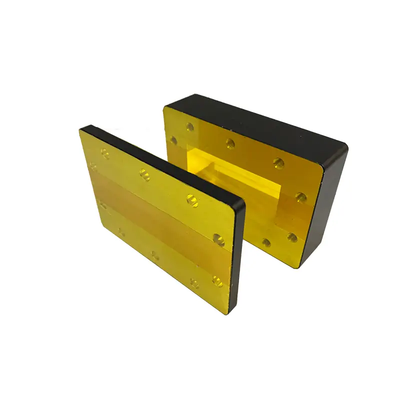
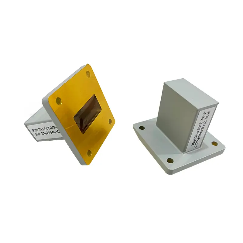
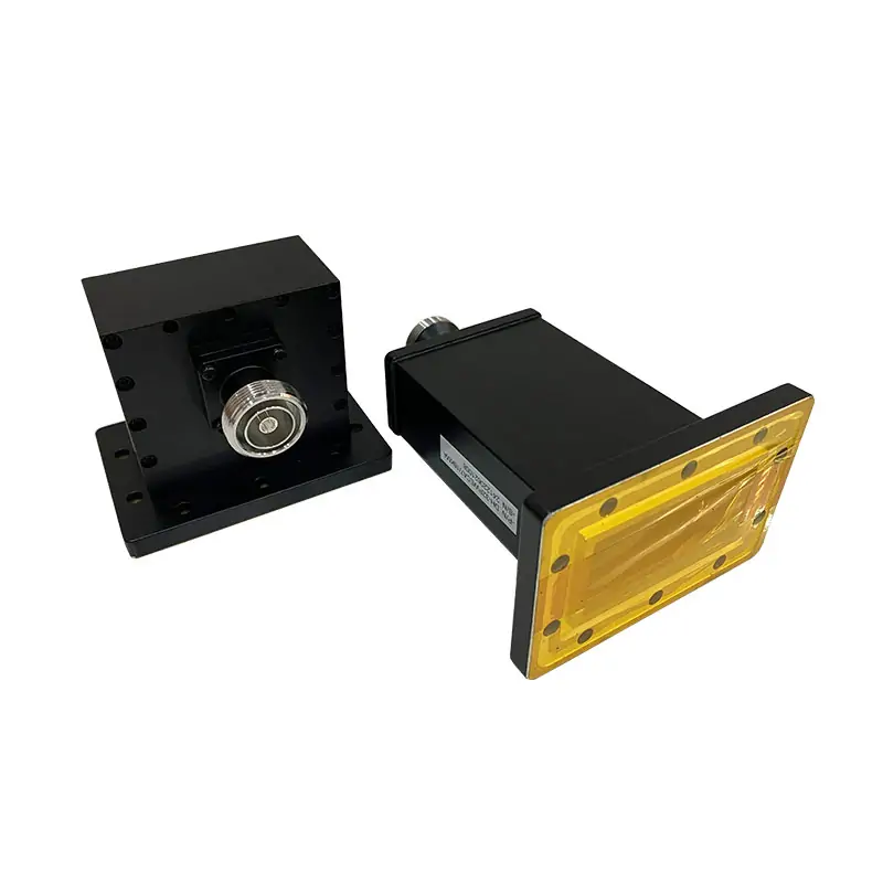
Precision Fixed Attenuator Range
Use this series for double-ridged waveguide paths from 0.84 to 40 GHz. Published models keep the same 3–40 dB attenuation range, 1.15:1 maximum VSWR and ±1.5 dB frequency response while waveguide size, flange designation, material and CW power entry change by model.
Published body materials are Al or Al/Cu. Standard finish includes Surtec/corrosion protection, flat black paint and unplated polished Surtec-treated flanges. Other finishes and paint colors are available on request.
Published Model Matrix
Match the frequency row first, then confirm attenuation, CW power, both flange designations and material. The power column is shown in watts; the ordering code defines “100” as 100 W CW.
| MODEL | FREQ. RANGE (GHz) | WG SIZE | VSWR Max. | ATT. (dB) | FREQ. RESPONSE (dB) | AVG POWER CW (W) | FLANGES TYPE COVER | FLANGES TYPE GROOVED | MATERIAL | FINISH | DWG | STEP |
|---|---|---|---|---|---|---|---|---|---|---|---|---|
| DH-840DRWFA… | 0.84-2.0 | WRD840 | 1.15:1 | 3-40 | ±1.5 | 100 | FPWRD840U24 | FMWRD840U24 | Al | Chromate/Painted | DWG | STEP |
| DH-150DRWFA… | 1.5-3.6 | WRD150 | 1.15:1 | 3-40 | ±1.5 | 100 | FPWRD150D24 | FMWRD150D24 | Al | Chromate/Painted | DWG | STEP |
| DH-200DRWFA… | 2.0-4.8 | WRD200 | 1.15:1 | 3-40 | ±1.5 | 100 | FPWRD200D24 | FMWRD200D24 | Al | Chromate/Painted | DWG | STEP |
| DH-250DRWFA… | 2.6-7.8 | WRD250 | 1.15:1 | 3-40 | ±1.5 | 100 | FPWRD250D30 | FMWRD250D30 | Al | Chromate/Painted | DWG | STEP |
| DH-350DRWFA… | 3.5-8.2 | WRD350 | 1.15:1 | 3-40 | ±1.5 | 100 | FPWRD350D24 | FMWRD350D24 | Al | Chromate/Painted | DWG | STEP |
| DH-475DRWFA… | 4.75-11.0 | WRD475 | 1.15:1 | 3-40 | ±1.5 | 100 | FPWRD475D24 | FMWRD475D24 | Al | Chromate/Painted | DWG | STEP |
| DH-500DRWFA… | 5.0-18.0 | WRD500 | 1.15:1 | 3-40 | ±1.5 | 100 | FPWRD500D36 | FMWRD500D36 | Al | Chromate/Painted | DWG | STEP |
| DH-580DRWFA… | 5.8-16.0 | WRD580 | 1.15:1 | 3-40 | ±1.5 | 100 | FPWRD580D28 | FMWRD580D28 | Al | Chromate/Painted | DWG | STEP |
| DH-650DRWFA… | 6.5-18.0 | WRD650 | 1.15:1 | 3-40 | ±1.5 | 100 | FPWRD650D28 | FMWRD650D28 | Al/Cu | Chromate/Painted | DWG | STEP |
| DH-700DRWFA… | 7.0-18.5 | WRD700 | 1.15:1 | 3-40 | ±1.5 | 100 | FPWRD700D26 | FMWRD700D26 | Al/Cu | Chromate/Painted | DWG | STEP |
| DH-750DRWFA… | 7.5-18.0 | WRD750 | 1.15:1 | 3-40 | ±1.5 | 100 | FPWRD750D24 | FMWRD750D24 | Al/Cu | Chromate/Painted | DWG | STEP |
| DH-110DRWFA… | 11.0-26.5 | WRD110 | 1.15:1 | 3-40 | ±1.5 | 50 | FPWRD110C24 | FMWRD110C24 | Al/Cu | Chromate/Painted | DWG | STEP |
| DH-180DRWFA… | 18.0-40.0 | WRD180 | 1.15:1 | 3-40 | ±1.5 | 50 | FPWRD180C24 | FMWRD180C24 | Al/Cu | Chromate/Painted | DWG | STEP |
Need standard rectangular waveguide instead of double-ridged? Use the Waveguide Fixed Attenuator range.
Check a ModelPart Number Guide
Use the code to lock the waveguide size, attenuator family, dB value, flange pair, material and CW rating in one line.
Manufacturing and Verification
For this attenuator family, the items worth locking before release are the RF band, attenuation value, flange interfaces, body material, finish and the required drawing or STEP file. Dimensional inspection and RF verification are handled within Dolph’s manufacturing and test setup. For drawing-based replacement or modified-interface work, see Waveguide Components Sales.
Dolph Microwave has manufactured waveguide and antenna products since 2001 and provides a one-year warranty against defective material and workmanship, subject to its warranty terms.
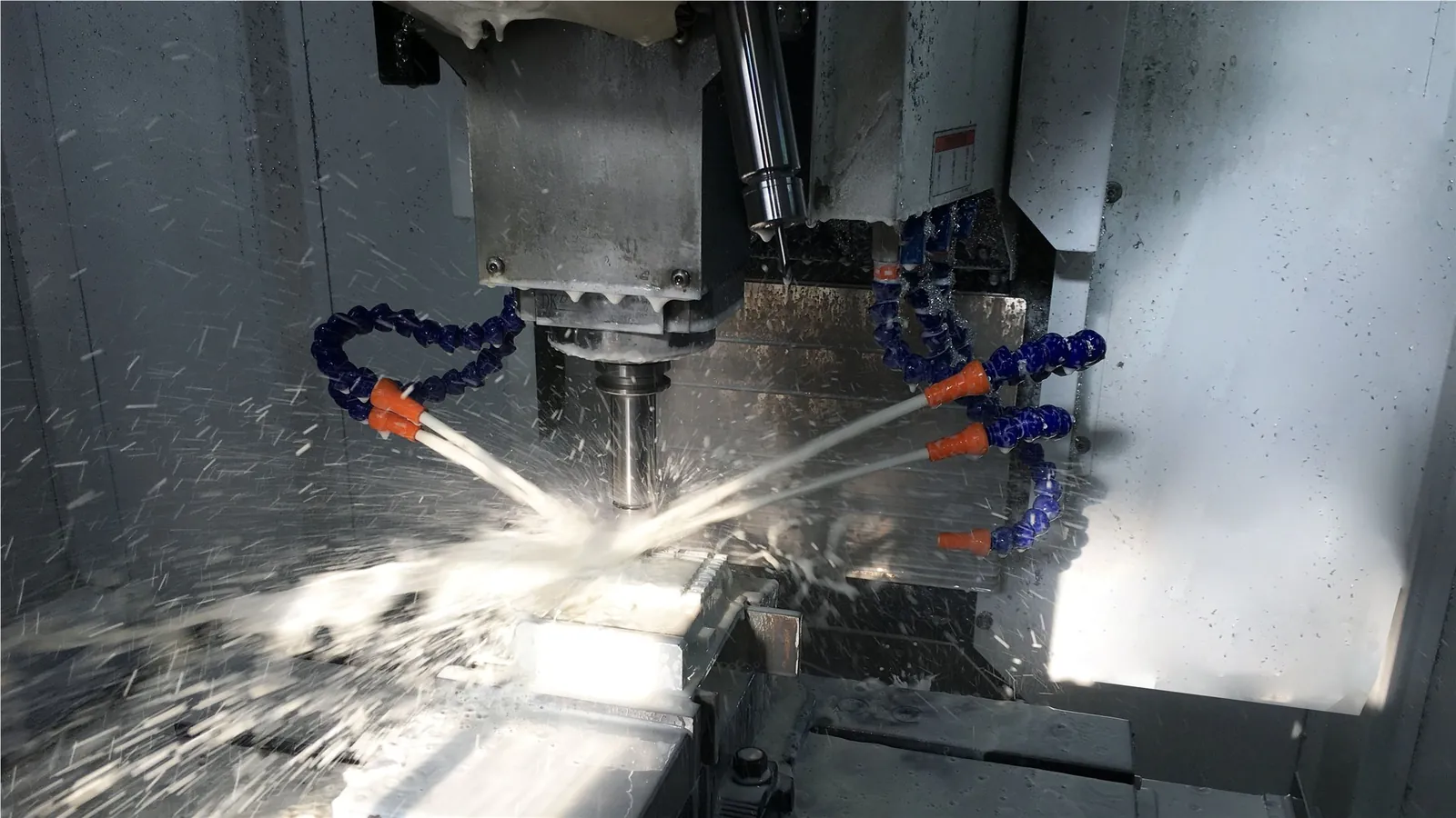

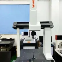
CNC milling, turning and waveguide forming are listed in Dolph’s manufacturing capabilities.
Brazing, soldering, plating, anodising and passivation are supported in the factory process set.
Use the approved model drawing and required RF data as the acceptance basis for your order.
Send the Inputs That Define the Build
A complete RFQ lets engineering confirm the model without guessing about power or interfaces. For pulsed systems, include peak power, pulse width and pulse repetition rate in addition to CW or average power.
Send RequirementsMinimum and maximum frequency, plus the required WRD size if already fixed.
Nominal dB value within the published 3–40 dB range.
CW power. For pulse service, add peak power, pulse width and repetition rate.
Flange at each end, quantity, envelope limits, and DWG or STEP requirements.
Check Waveguide Power Handling when the application includes pulse power, duty cycle, pressure or cooling limits.
Choose the Adjacent Component When the Requirement Changes
Stay with this precision fixed series for the published WRD840–WRD180, 3–40 dB configuration. Move to the related family below only when the power class, interface type or RF function changes.

High Power Fixed Attenuator
Use the high-power double-ridged family when the required CW power is above the precision fixed series and the attenuation range or thermal design must change.
Waveguide Fixed Attenuator
For standard rectangular waveguide rather than a double-ridged interface.
High-Power Waveguide Coaxial Adapter
For a double-ridged waveguide-to-coaxial transition instead of attenuation.
Precision Low Power Termination
For terminating the line rather than passing the signal through a fixed attenuation section.
Precision Waveguide Calibration Kits
For matching double-ridged calibration standards in a measurement setup.
Browse the full Double-Ridged Waveguide family for bends, transitions, couplers, switches, pressure components and other path hardware.

Technical References for Final Selection
Use it when CW power, peak power, duty cycle, pressure or cooling affects selection.
Use it to cross-check the required waveguide band before locking a model.
Use it when the mating flange designation or gasket fit still needs to be confirmed.
Use this route when the attenuator must be integrated into a custom assembly or matched to a drawing.
Ready for a Model Check or Custom Build
Send the operating band, attenuation, CW or pulse power, flange at each end, quantity and any mechanical drawing. Dolph can quote a published model or review a custom waveguide assembly when the catalog geometry does not fit.
Technical Downloads
Keep the flange reference with the RFQ so the mating interfaces are defined before the final model and drawing are released.