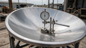
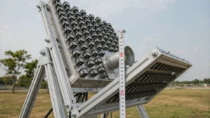
Maintain a ground-based satellite antenna by checking its reflector, feed cover, seals, drainage and cables without changing the RF geometry. At 12–30 GHz, assess loss in dB and surface error in mm against the antenna specification. Follow the approved cleaning procedure; an IEC 60529 enclosure rating does not define a universal cleaning method.
This guide concerns the outdoor antenna serving a satellite internet terminal. The indoor WiFi network is a separate link; cleaning the dish will not resolve local wireless interference or router faults.
How should you prepare the antenna before cleaning?
Establish a safe maintenance state and record the link condition before touching the antenna.
For a transmitting or motorized system, authorized personnel must control RF transmission and drive motion using the site procedure. A modem disconnect alone does not establish electrical or RF isolation. SLAC National Accelerator Laboratory’s RF lockout guidance illustrates the need for equipment-specific isolation, qualified personnel and post-work inspection; apply the procedure approved for your own installation.[1]
Photograph the reflector, feed cover, seals and cable routing. Record the modem’s actual metric and units, frequency or channel, weather, pointing status and alarms. Keep a reported signal-quality percentage separate from a measured dB value.
For earth station antennas, identify the reflector material, coating, feed arrangement and drive system from the model documentation. Use trained personnel and approved access equipment for elevated or large structures.
How should loose dirt be removed from the reflector?
Remove contamination with the tools and cleaning agent approved for the reflector’s actual surface finish.
Where the manual permits contact cleaning, use a clean, nonabrasive cloth or soft brush and minimal pressure. Do not drag grit across the surface. Use water or a mild detergent only when approved for the coating, radome and seals, and prevent liquid from entering feed openings or electrical equipment.
A reflector is not a mirror that must be polished to a shine. Abrasive pads, metal scrapers, pressure washing and unapproved solvents can damage its finish or geometry. Do not apply an annual UV spray, wax or replacement coating unless the manufacturer specifies it for that antenna.
Set the inspection interval from the manual, environment and maintenance history. Inspect after a contamination event such as a dust storm or nearby construction; there is no universal 72-hour or quarterly cleaning rule for every site.
How should the feed cover and seals be inspected?
Inspect for damage, moisture paths and loose interfaces without disturbing protected RF surfaces.
Check the feed cover or radome for cracks, displaced seals, trapped water and damaged fasteners. Do not open a sealed feed or insert swabs into a horn as routine cleaning. If water has entered the RF path, stop and arrange inspection under the equipment service procedure.
Replace a damaged seal with the approved part and installation method. Match waveguide gaskets to the actual flange groove and required sealing function. A thumbnail scratch, UV fluorescence or guessed compression percentage is not an acceptance test.
IEC 60529 classifies enclosure protection. An IP designation does not establish the present condition of an aged seal or authorize a different cleaning chemical or pressure-washing method.[2]
How should snow, ice and blocked drainage be handled?
Use the antenna’s approved snow-removal or de-icing method and keep designed drainage paths clear.
Do not chip ice from a reflector, pour hot water onto a feed cover, or improvise an RF heating system. If a fitted heater is present, inspect and operate it according to its manual. A heater fault requires troubleshooting before the equipment returns to service.
Remove accessible loose debris from drainage paths without changing openings, seals or mounting angles. Leave bonded ice or inaccessible deposits for qualified service personnel when the manual provides no safe removal procedure. Avoid loading the reflector with tools, body weight or a ladder.
How should cables and drive hardware be checked after cleaning?
Check cable support, weather protection and mechanical condition before restoring the recorded operating configuration.
Look for cracked jackets, loose connector weatherproofing, unsupported cable weight and rubbing at moving parts. Preserve the specified bend radius and strain relief. Do not rotate a connector to reposition a cable, spray chemicals into joints, or retighten every fastener to a generic torque value.
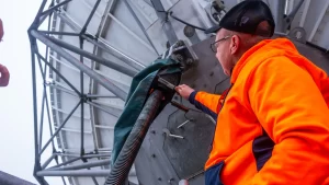
Restore service through the site’s release procedure and compare the same receiver metric under similar weather and pointing conditions. For the antenna’s RF assembly, review the feed-network interfaces if persistent loss remains after visible contamination and cable faults have been addressed.
| Finding after maintenance | Next check | What not to conclude |
|---|---|---|
| Signal changes during rain | Weather, wet surfaces, pointing and link alarms | That cleaning alone corrected the RF path |
| Moisture inside a feed enclosure | Seal, cover, drainage and approved service inspection | That an old IP label proves the enclosure is intact |
| Signal varies with antenna movement | Cable routing, connector support and drive behavior | That the reflector needs more scrubbing |
| Permanent dent or displaced panel | Reflector geometry and model-specific alignment criteria | That a cosmetic coating will restore the RF shape |
Why must cleaning preserve the reflector’s shape?
Surface deformation can reduce reflector gain, with the same geometric error becoming more significant as wavelength decreases.
For an illustrative random surface-error model, the relative gain factor is exp[−(4πσ/λ)2]. With RMS error σ = 0.25 mm, the calculated loss is:
| Frequency | Free-space wavelength | Calculated surface-error loss |
|---|---|---|
| 12 GHz | 24.98 mm | 0.069 dB |
| 20 GHz | 14.99 mm | 0.191 dB |
| 30 GHz | 9.99 mm | 0.429 dB |
These are calculations, not Dolph measurements, dirt-thickness limits or tolerances for a specific antenna. The Ruze approximation assumes a suitable random error distribution; NASA discusses why it may not represent concentrated or systematic deformation.[3] Use the antenna drawing and measured performance for an acceptance decision.
What else should operators know about antenna cleaning?
Cleaning should address an observed condition while preserving the manufacturer’s materials, geometry and service requirements.
Table of Contents
Will cleaning the dish improve indoor WiFi speed?
Only if contamination was affecting the satellite link. Compare the modem’s satellite-link readings separately from the indoor network. Router placement, local interference, device capability and service congestion can limit speed even when the outdoor antenna is clean and correctly aligned.
Can isopropyl alcohol be used on every feed cover?
No. Obtain the cleaning instructions for the actual cover, coating, adhesive and seal. A solvent suitable for one material may be unsuitable for another assembly. Do not infer compatibility from a generic material name or a cleaning method used on a different antenna.
Is there a universal dust thickness that requires cleaning?
No. The effect depends on coverage, moisture, composition, frequency and location. A dust layer on a radome is not equivalent to reflector shape error. Use inspection records, equipment guidance and comparable link measurements instead of converting an assumed dust thickness into a guaranteed dB loss.
What should accompany an RFQ for damaged feed components?
Send the antenna model, receive and transmit bands, feed or flange drawings, photographs and observed alarms. Include the environment and any evidence of water ingress or mechanical damage. Ask for interface and material confirmation before selecting a replacement from appearance alone.
Need to identify a replacement feed or waveguide interface? Send the model, frequency plan, flange drawing and damage photos to sales@dolphmicrowave.com, or submit the component inquiry.