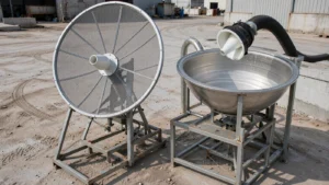
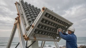
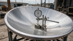
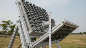
Maintain a flat plate antenna by isolating the equipment, inspecting its surface, checking mounts and fasteners, examining cables, assessing seals, comparing RF performance with a baseline and recording the results. Use the antenna manufacturer’s limits and cleaning procedure. A universal six-month interval, torque value or VSWR threshold cannot cover every installation.
How should the seven maintenance steps be organized?
Use a recorded inspection sequence that separates physical condition from RF performance and follows the equipment’s service procedure.
Identify the antenna, installation and approved maintenance instructions before starting. The checklist below supports planning; it does not authorize opening a sealed array, working on an energized transmitter or applying an unapproved cleaning chemical.
| Step | Action | Record or decision |
|---|---|---|
| 1. Isolate and identify | Use the equipment procedure; identify ports and model | Work authorization and configuration |
| 2. Inspect the surface | Look for cracks, deposits, delamination or impact | Location and photographs of defects |
| 3. Check mounts and fasteners | Inspect looseness, corrosion and alignment | Approved torque/hardware action if required |
| 4. Inspect cables and connectors | Check strain, bend damage and moisture | Connection and cable condition |
| 5. Check seals and drainage | Inspect accessible seals and water paths | Replacement or service requirement |
| 6. Compare RF performance | Measure under repeatable conditions | Baseline difference and uncertainty |
| 7. Document and follow up | Record actions, parts and remaining issues | Return-to-service decision and next inspection |
What cleaning and mechanical checks are appropriate?
Use only the cleaning materials and mechanical procedures approved for that antenna and its radome or coating.
Inspect before cleaning so damage is not hidden or spread. Avoid forcing particles or moisture into connectors and seams. Do not scrape RF surfaces or apply lubricants to seals and fasteners without the specified procedure. A sealed array may require factory service instead of field disassembly.
Check mounting orientation and support condition against the installation record. Repeatedly tightening every screw is not a substitute for identifying loose hardware, thread damage or a joint that has moved. NASA’s fastener guidance shows why finish, lubrication and preload must be considered together.[1]
How can RF checks distinguish antenna damage from setup changes?
Repeat the baseline conditions before attributing a measured difference to the antenna.
Use the same frequency points, reference plane, polarization, alignment and cable arrangement. Record environmental changes and nearby obstructions. Measure input match separately from the radiated link or pattern; a return-loss check alone cannot reveal every array or polarization fault.
For a defined gain-comparison setup, use a suitable standard gain reference antenna. If the installation includes a separate antenna feeder network, inspect its interfaces and measurement contribution before replacing the antenna.
NIST’s antenna-measurement work describes combining uncertainty contributions. Small apparent changes should be assessed against that uncertainty and the project’s acceptance limit.[2]
What determines the maintenance interval and return to service?
The manufacturer’s instructions, environment, service history and observed condition determine the schedule and corrective action.
Increase inspection attention after impact, water ingress or an abnormal RF event according to the service procedure. Record as-found and as-left conditions, replaced parts and unresolved deviations. Do not declare the antenna restored solely because a connector was reseated or a signal reappeared.
Table of Contents
Should every flat plate antenna meet VSWR below 1.5:1?
Use the specified limit for the antenna, band and reference plane. A universal number can reject valid equipment or accept a fault outside the checked band. Compare the measured sweep with the approved specification and the established baseline under repeatable conditions.
Can solvent or compressed air be used for cleaning?
Only when the manufacturer’s service procedure permits the method and conditions. Coatings, radomes, seals and connectors can respond differently. Start with inspection and the approved cleaning instructions; do not use a generic solvent mixture or pressure setting from another antenna design.
What should a maintenance record contain?
Record model and serial identification, date, environment, photographs, defects, approved actions and any replaced parts. Include RF setup details, calibration state, baseline comparison and unresolved issues. This allows the next technician to distinguish recurring damage from a change in measurement conditions.
Send the antenna model, feed-interface drawing, inspection findings and measured RF changes when requesting compatible feed or waveguide replacement components.