Waveguide flange selection starts with the mating interface: cover or contact, pressure-sealing, or choke geometry. Match the aperture, bolt pattern, alignment features and specified standard before comparing RF performance. At 30 GHz, a 0.1 mm offset is 1% of free-space wavelength; that calculation illustrates scale, not an allowable alignment tolerance.
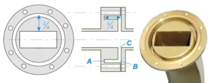
What are the main waveguide flange configurations?
The useful distinction is how the joint carries RF current and provides sealing, rather than whether its outside profile is round or square.
| Configuration | Function | Selection check |
|---|---|---|
| Cover or contact interface | Joins waveguide sections through the specified mating faces | Aperture, face condition, hole pattern and alignment |
| Pressure-sealing interface | Accommodates the specified gasket arrangement to maintain a pressure boundary | Seal type, groove, mating face and complete-joint pressure test |
| Choke interface | Uses designed groove geometry as part of the RF connection | Approved mating configuration, operating band and groove dimensions |
| Precision millimeter-wave interface | Controls aperture alignment for small waveguides and repeatable connections | Exact flange variant, alignment features and dimensional tolerances |
These descriptions overlap: a choke assembly may also incorporate a pressure seal, and a cover flange can be circular or square. MIL-DTL-3922’s associated sheets distinguish cover, choke, pressurizable-contact and millimeter-wave configurations. Use the individual drawing, not the broad family name, to establish compatibility.[1]
How do you match flange standards and part numbers?
Match the complete designation and controlled drawing on both ends; a shared waveguide size does not prove that two flanges mate correctly.
IEC 60154-2 specifies flange dimensions and mechanical compatibility for ordinary rectangular waveguides. MIL-DTL-3922 gives general requirements for waveguide flanges that mechanically and electrically connect sections. Neither document title alone identifies a specific flange or proves that a supplied component conforms.[2][3]
- Record the waveguide cross-section and full flange code, including suffixes.
- Check aperture dimensions, bolt positions, hole diameters and threaded versus clearance holes.
- Check alignment pins and holes, including which member provides each feature.
- Compare seal and choke grooves, face steps and gasket location.
- Confirm the drawing revision and any adapter required between unlike interfaces.
When reviewing standard waveguide components, specify each end separately. An assembly can have the same aperture at both ends but different flange interfaces.
Why do flange alignment and face condition matter?
An offset, gap or damaged contact surface creates a discontinuity at the joint, so repeatable mechanical assembly is part of repeatable RF performance.
The following wavelength comparison uses λ = c/f with c rounded to 300 mm·GHz. It is a scaling example, not an acceptance table; allowable errors depend on the waveguide dimensions, mode, interface design and required match.
| Frequency | Free-space wavelength | 0.1 mm offset as a fraction of wavelength |
|---|---|---|
| 10 GHz | 30 mm | 0.33% |
| 30 GHz | 10 mm | 1.00% |
| 100 GHz | 3 mm | 3.33% |
Inspect the aperture edges, contact faces and alignment features before tightening. Remove debris using the approved cleaning procedure. Do not draw misaligned sections together by tightening bolts; correct the mechanical support and mating alignment first.
Specify torque from the approved assembly procedure. A torque value copied from another flange can overload a smaller fastener or leave insufficient clamp load. If controlled spacing is required, select a drawing-matched waveguide flange shim rather than adding an arbitrary washer or sheet.
How do pressure seals and choke grooves differ?
A pressure seal restricts gas leakage, while a choke groove forms part of the electromagnetic joint; the two functions require separate design checks.
Do not identify every recess as an O-ring groove. Verify its purpose on the drawing before fitting a seal or applying any compound. Gasket thickness, compression and position must suit the specified pair of mating flanges.
A pressure rating belongs to the validated assembly, not to the flange outline. If the system needs a barrier across the aperture, select and verify a waveguide pressure-window assembly together with its mating joints. A flange seal alone leaves the waveguide bore open.
How should a flange connection be accepted for RF use?
Accept the assembled connection against a defined frequency band, reference plane and mechanical procedure, using both reflection and transmission measurements where required.
Return loss describes reflection; insertion loss describes transmission reduction. For example, 20 dB return loss corresponds to 1% reflected power and approximately 1.22:1 VSWR. It does not establish a 0.01 dB insertion-loss rating. This is a mathematical conversion, not a Dolph product specification.
- Document calibration planes and any adapters included or corrected out.
- Measure the assembled path across the required band instead of using only a center-frequency point.
- For frequently disconnected interfaces, specify a reconnection sequence and compare the resulting spread.
- For pressurized systems, define leak-test conditions and acceptance separately from the RF limits.
- Retain the approved mating drawings and component identifiers with the test record.
What compatibility questions should buyers resolve?
Resolve the complete flange pair, seal arrangement and acceptance requirements before placing a replacement order.
Table of Contents
Do two WR90 flanges always connect directly?
No. WR90 identifies the waveguide size, not every feature of its flange. Compare the full flange designation, bolt pattern, alignment details, face geometry and sealing arrangement. A matching aperture does not eliminate the need for a controlled mating-interface check.
Is a choke flange always better than a cover flange?
No. Select the configuration specified for the operating band and mating joint. A choke relies on its designed geometry and compatible partner; it is not a universal upgrade. Check RF performance, sealing needs, size and maintenance conditions for the complete assembly.
Can I infer power handling from a flange code?
Not by itself. Power capability depends on the assembled waveguide path, frequency, pressure, temperature, surface condition and mismatch. State continuous and peak power conditions in the RFQ, then request the applicable component or assembly rating and supporting acceptance requirements.
What should a replacement-flange enquiry include?
Send drawings or clear photographs of both mating faces, the waveguide size, complete markings and required band. Add sealing conditions, material and finish requirements, available installation space and test limits. Identify missing dimensions so they can be resolved before manufacture.
Identify both mating interfaces before ordering. Send the flange drawings, frequency band, power conditions and sealing requirements for an interface review.