
HOME » Waveguide, RF & Microwave Components » Waveguide To Coaxial Adapter
Waveguide To Coaxial Adapter
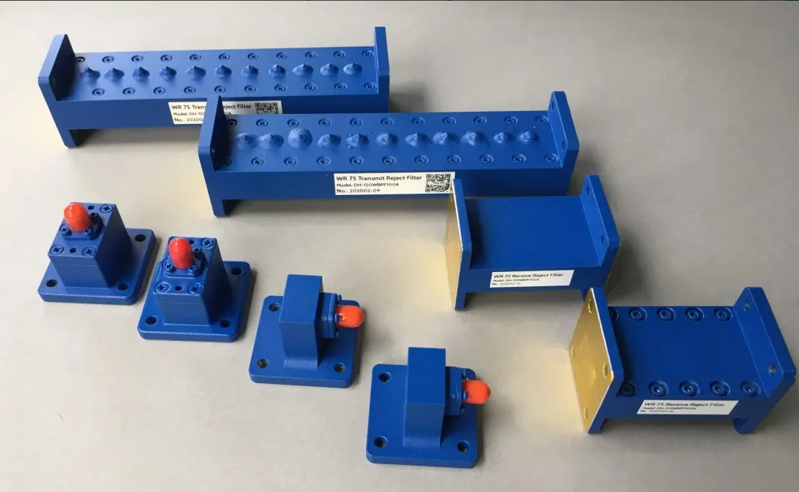
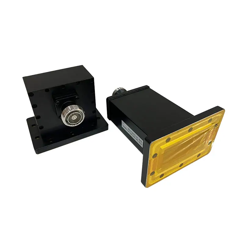
Double-ridged waveguide-to-coaxial adapters connect WRD assemblies to coaxial instruments or RF modules. WCA right-angle and WECA end-launch models cover individual bands within 0.84–40 GHz. Match the WRD size, flange and N, SMA or 2.92 mm interface; connector and power ratings vary by model.
Published Frequency
0.84–40.0 GHz
Waveguide Range
WRD840–WRD180
Published VSWR
1.25:1–1.40:1
Published IL
0.3–0.4 dB
Configurations
Right Angle / End Launch
Published Connectors
N / SMA / 2.92 mm
Waveguide–Coaxial Interface
Select the Launch Geometry, Connector and Flange
Right-Angle Adapter
The coaxial connector exits at a right angle to the waveguide axis. Use this arrangement where side access is required or axial clearance is limited.End-Launch Adapter
The coaxial connector aligns with the end-launch geometry. Confirm the available axial envelope, cable bend clearance and connector access.N-Female
Published on the lower-frequency WRD840 through WRD475 entries.SMA-Female
Published on WRD500 through WRD750 entries.2.92 mm Female
Published on WRD110 and WRD180 entries.Published Catalog Data
Double-Ridged Waveguide to Coaxial Adapter Range
Swipe horizontally to view all columns.
| WRD Family / Models | Frequency | VSWR | IL (dB) | Connector | Avg. Power (W) | Length (mm) | Cover Flange | Grooved Flange | RoHS & REACH |
|---|---|---|---|---|---|---|---|---|---|
| WRD840 DH-840DRWCA / WECA… | 0.84–2.0 | 1.25:1 | 0.3 | N-Female | 800 | 320 | FPWRD840U24 | FMWRD840U24 | Comply |
| WRD150 DH-150DRWCA / WECA… | 1.5–3.6 | 1.25:1 | 0.3 | N-Female | 800 | 150 | FPWRD150D24 | FMWRD150D24 | Comply |
| WRD200 DH-200DRWCA / WECA… | 2.0–4.8 | 1.40:1 | 0.3 | N-Female | 500 | 128 | FPWRD200D24 | FMWRD200D24 | Comply |
| WRD250 DH-250DRWCA / WECA… | 2.6–7.8 | 1.40:1 | 0.4 | N-Female | 500 | 98 | FPWRD250D30 | FMWRD250D30 | Comply |
| WRD350 DH-350DRWCA / WECA… | 3.5–8.2 | 1.40:1 | 0.4 | N-Female | 500 | 90 | FPWRD350D24 | FMWRD350D24 | Comply |
| WRD475 DH-475DRWCA / WECA… | 4.75–11.0 | 1.30:1 | 0.3 | N-Female | 300 | 70 | FPWRD475D24 | FMWRD475D24 | Comply |
| WRD500 DH-500DRWCA / WECA… | 5.0–18.0 | 1.30:1 | 0.3 | SMA-Female | 300 | 54 | FPWRD500D36 | FMWRD500D36 | Comply |
| WRD580 DH-580DRWCA / WECA… | 5.8–16.0 | 1.30:1 | 0.3 | SMA-Female | 300 | 50 | FPWRD580D28 | FMWRD580D28 | Comply |
| WRD650 DH-650DRWCA / WECA… | 6.5–18.0 | 1.25:1 | 0.3 | SMA-Female | 100 | 52 | FPWRD650D28 | FMWRD650D28 | Comply |
| WRD700 DH-700DRWCA / WECA… | 7.0–18.5 | 1.25:1 | 0.3 | SMA-Female | 100 | 55 | FPWRD700D26 | FMWRD700D26 | Comply |
| WRD750 DH-750DRWCA / WECA… | 7.5–18.0 | 1.30:1 | 0.3 | SMA-Female | 100 | 59 | FPWRD750D24 | FMWRD750D24 | Comply |
| WRD110 DH-110DRWCA / WECA… | 11.0–26.5 | 1.25:1 | 0.3 | 2.92-Female | 50 | 35 | FPWRD110C24 | FMWRD110C24 | Comply |
| WRD180 DH-180DRWCA / WECA… | 18.0–40.0 | 1.30:1 | 0.3 | 2.92-Female | 50 | 29 | FPWRD180C24 | FMWRD180C24 | Comply |
Selection note: published connector, power and length values vary by WRD family. Alternative connectors mentioned elsewhere on the page should be treated as request options unless they appear in the selected model drawing or quotation.
Interface Review
Three Interfaces Must Be Defined Together
WRD and Flange
Select the WRD family plus cover or grooved flange designation.Connector Interface
Specify connector series, male or female interface and cable or mating-part constraints.Launch Direction
Choose WCA or WECA and confirm connector clearance, overall length and flange clocking.Ordering Code
Part Number Interpretation
Applications
Typical Adapter Uses
RF Test Interfaces
Connect coaxial instrumentation to a double-ridged waveguide test setup. Define the measurement reference plane and account for the adapter when calibrating; see RF test interface selection.Radar Subsystems
Transition between coaxial modules and broadband waveguide assemblies.Antenna Feed Networks
Provide a controlled interface between coaxial equipment and feed components.System Integration
Resolve mechanical routing constraints with right-angle or end-launch geometry.Specification-Based Quotation
Submit the WRD Family, Launch Geometry and Connector Interface
Include the operating band, WCA or WECA layout, connector gender, flange designation, quantity and acceptance requirements.Related products:Straights & TransitionsDouble-Ridged BendsDouble-Ridged Horn AntennasDouble-Ridged Components
| MODEL | FREQ. RANGE (GHz) | WG SIZE | VSWR | IL (dB) | CONNECTOR TYPE | AVG. POWER (W) | LENGTH (mm) | FLANGES TYPE | ROHS & REACH | DATASHEET | ||
| COVER | GROOVED | |||||||||||
| DH-840DRWCA… | 0.84-2.0 | WRD840 | 1.25:1 | 0.3 | N-Female | 800 | 320 | FPWRD840U24 | FMWRD840U24 | Comply | STEP | |
| DH-840DRWECA… | 0.84-2.0 | WRD840 | 1.25:1 | 0.3 | N-Female | 800 | 320 | FPWRD840U24 | FMWRD840U24 | Comply | STEP | |
| DH-150DRWCA… | 1.5-3.6 | WRD150 | 1.25:1 | 0.3 | N-Female | 800 | 150 | FPWRD150D24 | FMWRD150D24 | Comply | STEP | |
| DH-150DRWECA… | 1.5-3.6 | WRD150 | 1.25:1 | 0.3 | N-Female | 800 | 150 | FPWRD150D24 | FMWRD150D24 | Comply | STEP | |
| DH-200DRWCA… | 2.0-4.8 | WRD200 | 1.4:1 | 0.3 | N-Female | 500 | 128 | FPWRD200D24 | FMWRD200D24 | Comply | STEP | |
| DH-200DRWECA… | 2.0-4.8 | WRD200 | 1.4:1 | 0.3 | N-Female | 500 | 128 | FPWRD200D24 | FMWRD200D24 | Comply | STEP | |
| DH-250DRWCA… | 2.6-7.8 | WRD250 | 1.4:1 | 0.4 | N-Female | 500 | 98 | FPWRD250D30 | FMWRD250D30 | Comply | STEP | |
| DH-250DRWECA… | 2.6-7.8 | WRD250 | 1.4:1 | 0.4 | N-Female | 500 | 98 | FPWRD250D30 | FMWRD250D30 | Comply | STEP | |
| DH-350DRWCA… | 3.5-8.2 | WRD350 | 1.4:1 | 0.4 | N-Female | 500 | 90 | FPWRD350D24 | FMWRD350D24 | Comply | STEP | |
| DH-350DRWECA… | 3.5-8.2 | WRD350 | 1.4:1 | 0.4 | N-Female | 500 | 90 | FPWRD350D24 | FMWRD350D24 | Comply | STEP | |
| DH-475DRWCA… | 4.75-11.0 | WRD475 | 1.3:1 | 0.3 | N-Female | 300 | 70 | FPWRD475D24 | FMWRD475D24 | Comply | STEP | |
| DH-475DRWECA… | 4.75-11.0 | WRD475 | 1.3:1 | 0.3 | N-Female | 300 | 70 | FPWRD475D24 | FMWRD475D24 | Comply | STEP | |
| DH-500DRWCA… | 5.0-18.0 | WRD500 | 1.3:1 | 0.3 | SMA-Female | 300 | 54 | FPWRD500D36 | FMWRD500D36 | Comply | STEP | |
| DH-500DRWECA… | 5.0-18.0 | WRD500 | 1.3:1 | 0.3 | SMA-Female | 300 | 54 | FPWRD500D36 | FMWRD500D36 | Comply | STEP | |
| DH-580DRWCA… | 5.8-16.0 | WRD580 | 1.3:1 | 0.3 | SMA-Female | 300 | 50 | FPWRD580D28 | FMWRD580D28 | Comply | STEP | |
| DH-580DRWECA… | 5.8-16.0 | WRD580 | 1.3:1 | 0.3 | SMA-Female | 300 | 50 | FPWRD580D28 | FMWRD580D28 | Comply | STEP | |
| DH-650DRWCA… | 6.5-18.0 | WRD650 | 1.25:1 | 0.3 | SMA-Female | 100 | 52 | FPWRD650D28 | FMWRD650D28 | Comply | STEP | |
| DH-650DRWECA… | 6.5-18.0 | WRD650 | 1.25:1 | 0.3 | SMA-Female | 100 | 52 | FPWRD650D28 | FMWRD650D28 | Comply | STEP | |
| DH-700DRWCA… | 7.0-18.5 | WRD700 | 1.25:1 | 0.3 | SMA-Female | 100 | 55 | FPWRD700D26 | FMWRD700D26 | Comply | STEP | |
| DH-700DRWECA… | 7.0-18.5 | WRD700 | 1.25:1 | 0.3 | SMA-Female | 100 | 55 | FPWRD700D26 | FMWRD700D26 | Comply | STEP | |
| DH-750DRWCA… | 7.5-18.0 | WRD750 | 1.3:1 | 0.3 | SMA-Female | 100 | 59 | FPWRD750D24 | FMWRD750D24 | Comply | STEP | |
| DH-750DRWECA… | 7.5-18.0 | WRD750 | 1.3:1 | 0.3 | SMA-Female | 100 | 59 | FPWRD750D24 | FMWRD750D24 | Comply | STEP | |
| DH-110DRWCA… | 11.0-26.5 | WRD110 | 1.25:1 | 0.3 | 2.92-Female | 50 | 35 | FPWRD110C24 | FMWRD110C24 | Comply | STEP | |
| DH-110DRWECA… | 11.0-26.5 | WRD110 | 1.25:1 | 0.3 | 2.92-Female | 50 | 35 | FPWRD110C24 | FMWRD110C24 | Comply | STEP | |
| DH-180DRWCA… | 18.0-40.0 | WRD180 | 1.30:1 | 0.3 | 2.92-Female | 50 | 29 | FPWRD180C24 | FMWRD180C24 | Comply | STEP | |
| DH-180DRWECA… | 18.0-40.0 | WRD180 | 1.30:1 | 0.3 | 2.92-Female | 50 | 29 | FPWRD180C24 | FMWRD180C24 | Comply | STEP | |
| Part Number Guide: DH-840DRWCANKPA "840DR"—Waveguide Size | WRD840 "WCA"—Waveguide Type | Right Angle Waveguide to Coaxial Adapter "WECA"—Waveguide Type | End Launch Waveguide to Coaxial Adapter "N"— Connector Type | N-type "T"— Connector Type | TNC-type "SMA"— Connector Type | SMA "2.92"— Connector Type | 2.92mm "K"— Interface Type | Female "J"— Interface Type | Male "P"— Flange Type | Rectangular Cover "M"— Flange Type | Rectangular Grooved "A/C"— Material | Aluminium, Cu |
||||||||||||
| Note: All Dolph-MW models include an surtec/corrosion protection treatment and are painted flat black. Flanges are unplated, polished and surtec. Other finishes and paint colors are available upon request. |
||||||||||||