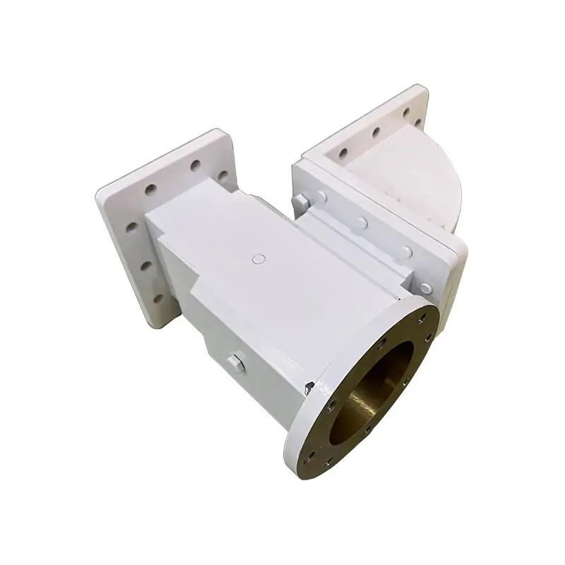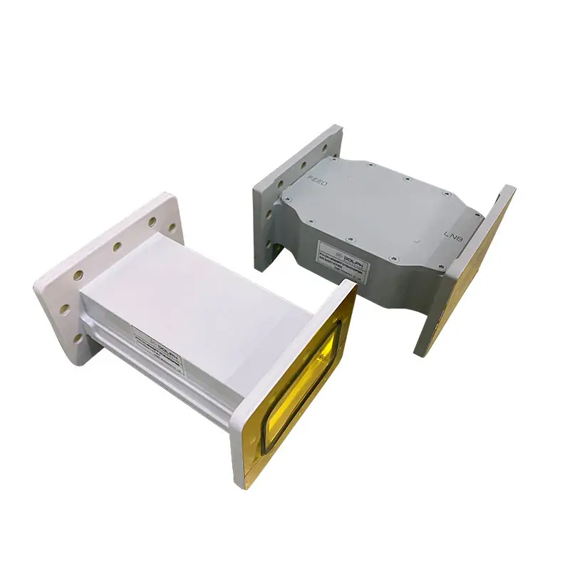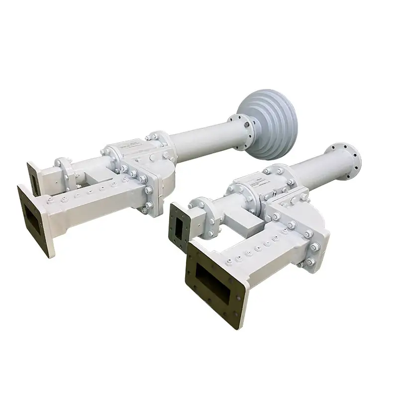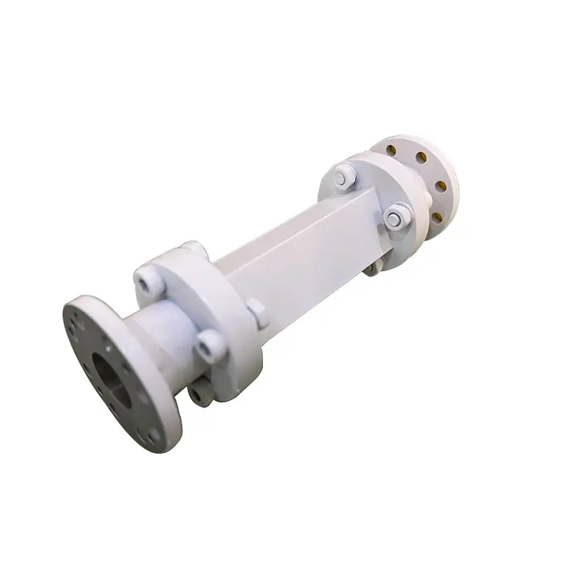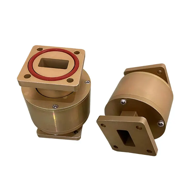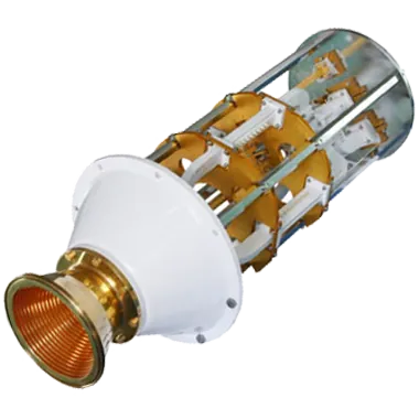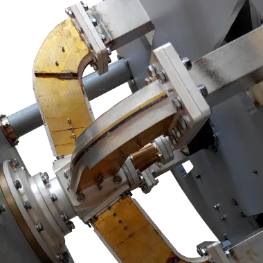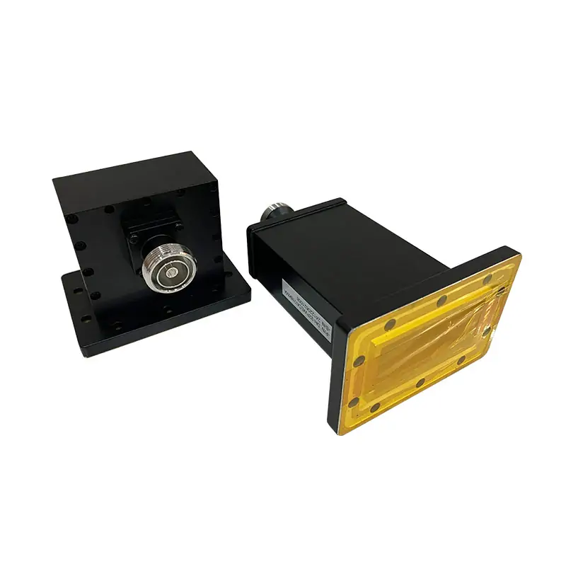
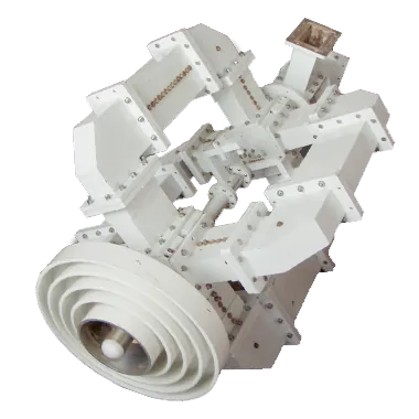
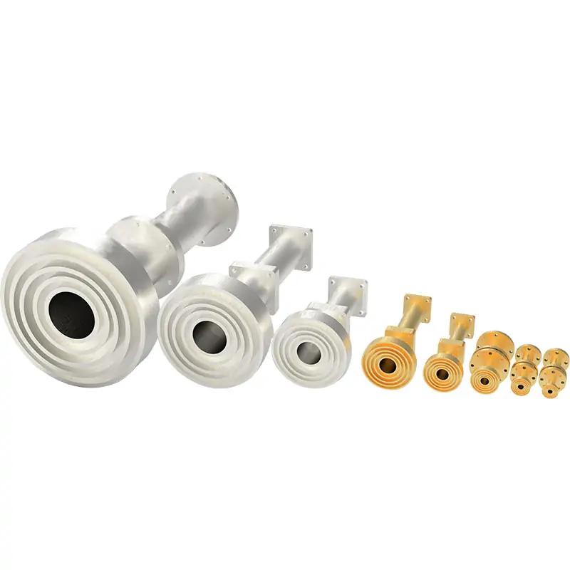
Microwave Feedhorn
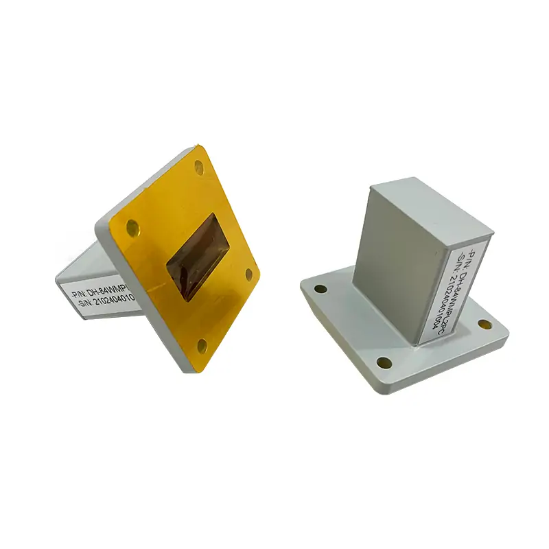
C, X, Ku and Ka-band feedhorn configurations are published, with linear/circular, dual or co-polarization options on the feedhorn product range.

We can supply the complete feed assembly or only the functions you need. The frequency plan, polarization, waveguide interfaces, available envelope and reflector geometry are reviewed together before the build is released.
The feed network can be built from Dolph microwave components as one matched mechanical and RF assembly.
C, X, Ku and Ka-band feedhorn configurations are published, with linear/circular, dual or co-polarization options on the feedhorn product range.
Used to separate or combine orthogonal polarization paths inside the feed network.
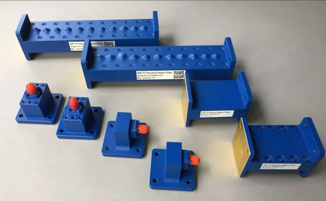
Added where the RF path requires controlled band selection or rejection.
Used to separate or combine transmit and receive paths in the feed chain.
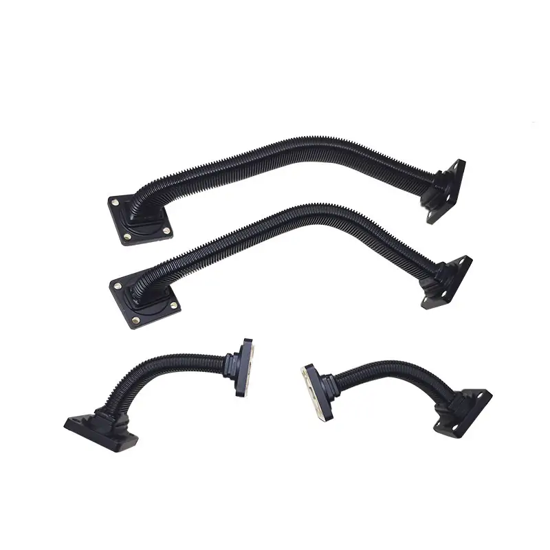
For phase and polarization functions inside circular or rectangular waveguide feed sections.
Supports RF transmission through rotating interfaces where the antenna architecture requires movement.
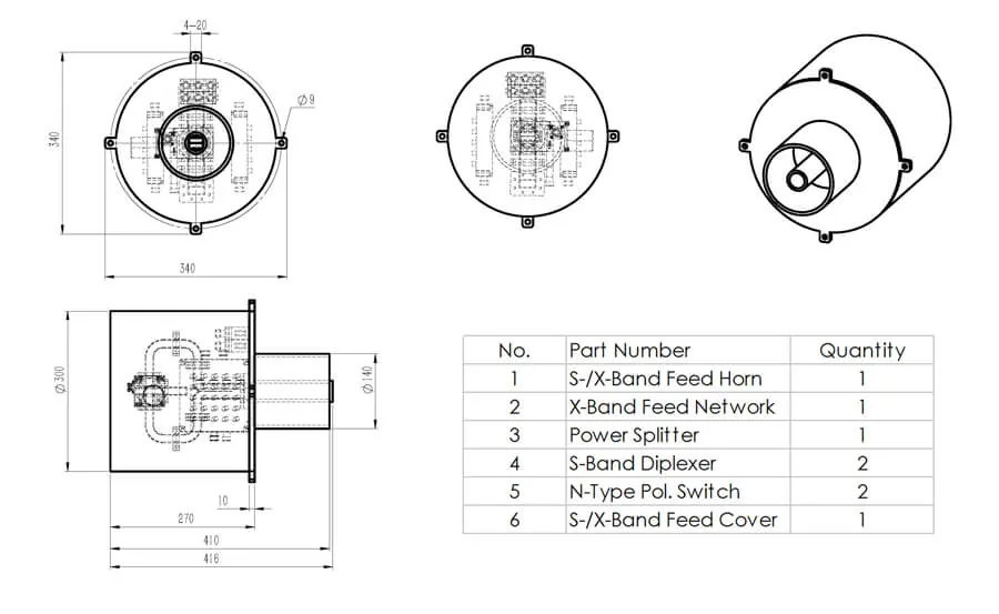
Dolph offers single-band, dual-band and triple-band antenna feed designs. Published feed-network work includes combined C/Ku, S/X, DBS, Ku/Ka and Ka examples.
This published S/X configuration is a project reference, not a universal rating. Confirm whether the Tx/Rx labels refer to the ground or spacecraft equipment, and identify the measured receive chain for the listed noise figure before using it in a link budget.
The catalog gives the following ordering example for a Ku-band transceiver feed assembly.
The catalog key also lists M as the grooved-flange designation.
A passive feed network routes signals by frequency and polarization between the RF equipment and antenna feed. Link distance and building penetration depend on the complete radio system and propagation path; they are not standalone feed-network specifications.
Send the available RF and mechanical inputs. If you only have a drawing, part number or partial specification, our engineering team can start from that.
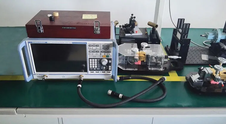
Dolph Microwave’s published manufacturing scope includes machining, forming, joining, finishing and RF/mechanical verification. Define the drawing revision, inspection points and RF acceptance tests for the selected feed assembly.
Dolph’s published application scope for antenna feeder networks includes the areas below.
Establishing and maintaining satellite communication links for data, voice and video transmission.
Monitoring and collecting environmental data for climate research, natural-disaster assessment and resource management.
Communication with spacecraft exploring the solar system and beyond.
Radio-wavelength observation within research antenna systems.
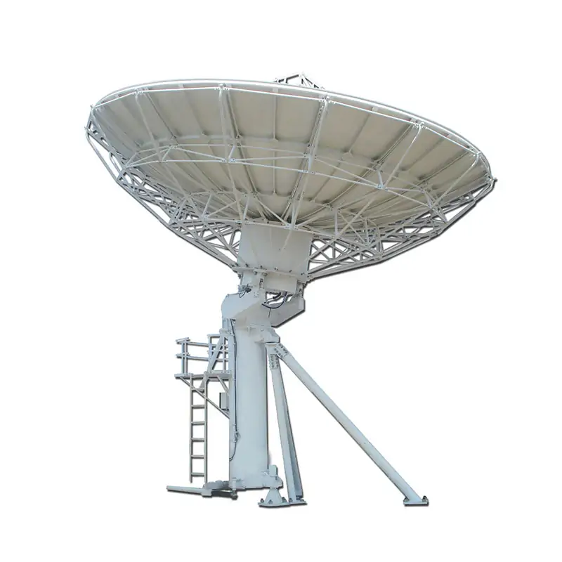
Use this range when the reflector antenna and feeder network need to be reviewed in the same project scope.
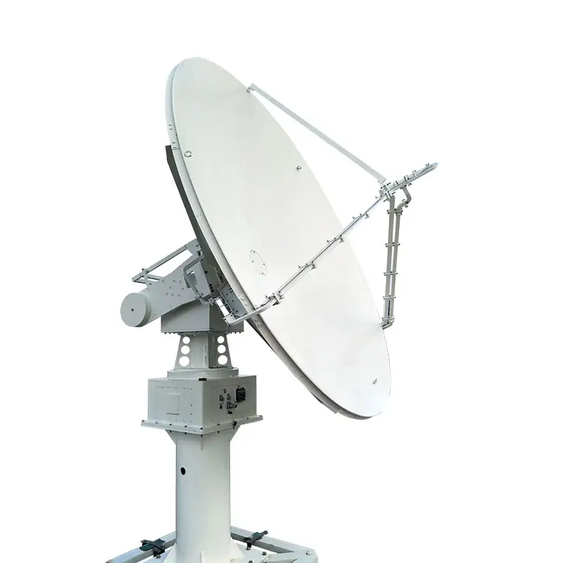
Use this range when the application requires a tracking antenna rather than a feed-only assembly.
Request current quality-system, compliance and warranty documents for supplier qualification.

Request current quality-system documentation.

Request the applicable process-compliance documentation.

Published product information describes a one-year warranty against defective material and workmanship. Confirm the start date, coverage and return conditions in the quotation and applicable warranty terms.
For a complete feed-only project beyond the published configurations, use our Custom Antenna Feed Systems capability. If you need a discrete function, review the Microwave Feedhorn, OMT, Waveguide Filter or Waveguide Diplexer.
Send the frequency plan, polarization, reflector type, interfaces, power level and quantity you have. We will use those inputs to review the right feed-network scope with you.