
Quick-Deploy and Vehicle-Mounted SATCOM Antennas
Select a deployable antenna by how it is transported, mounted, pointed and operated. Dolph Microwave lists auto-acquisition, driveaway, flyaway and larger quick-deploy configurations. Deployment time, pointing accuracy, wind limits and in-motion operation must be confirmed for the selected model.
Choose the product family

0.9 / 1.2 m auto-acquisition antennas
Review the reflector option, acquisition method, controller and required operating band.
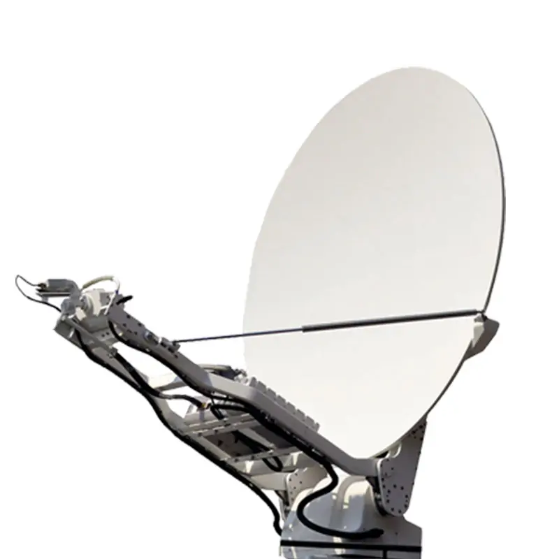
Vehicle-mounted driveaway antennas
Compare the listed reflector options with vehicle load, stowed space and deployment clearance.

1.2 m flyaway antenna
Use a transportable configuration when the antenna must be moved and assembled at the site.
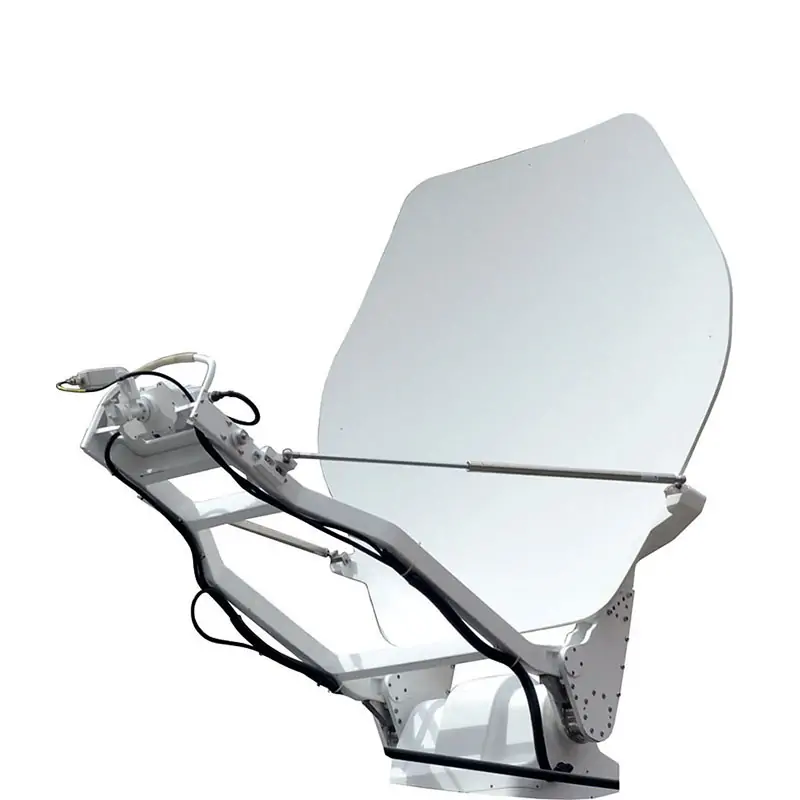
1.8 / 2.4 m quick-deploy antennas
Check transport, assembly, pointing and feed requirements for the larger reflector options.
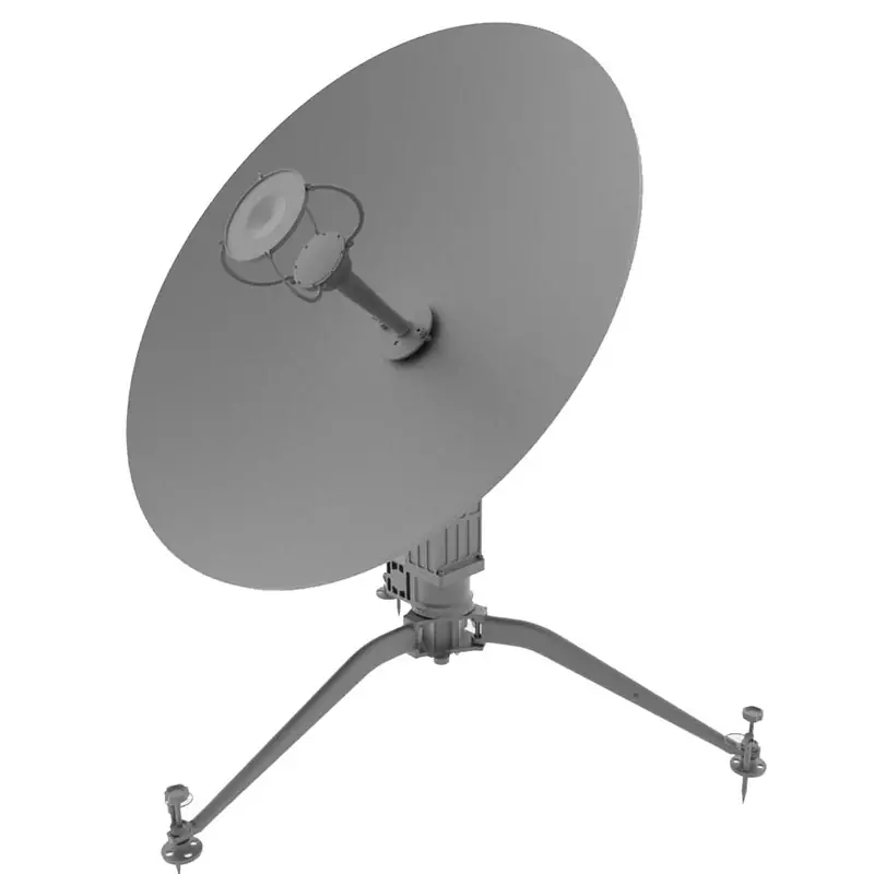
Motorized flyaway antenna
Confirm the drive system, control interface, power supply and the intended deployment procedure.

Feed-network configuration
Specify receive and transmit paths, polarization, RF connections and power requirements.
Define the operating mode first
“Driveaway” describes a vehicle-mounted deployment arrangement; it does not by itself establish satellite operation while moving. State whether the terminal operates only after parking or requires tracking during motion. Confirm that capability explicitly on the quotation and test specification.
Automatic acquisition also needs compatible controls and system inputs. Identify the controller, modem or beacon interface and the expected pointing procedure instead of assuming every antenna uses the same method.
RFQ checklist for a deployable terminal
| Selection input | What to specify |
|---|---|
| RF configuration | Receive/transmit bands, polarization, feed ports and BUC/LNB or transceiver interfaces. |
| Transport and mounting | Vehicle or transport case, permitted load, mounting drawing and stowed dimensions. |
| Deployment space | Operating envelope, overhead clearance, access for assembly and any mounting restrictions. |
| Pointing and tracking | Manual or motorized positioning, acquisition inputs, tracking requirement and controller interface. |
| Power and environment | Available electrical supply, transmit duty, operating temperature and required wind or weather conditions. |
| Acceptance | Define deployment procedure, pointing test, RF performance and supplied records for the chosen configuration. |
Compare the complete antenna configuration
A larger reflector may change transport, mounting and pointing requirements. Compare the actual model data rather than transferring a smaller model’s deployment or environmental rating.
For fixed-site or orbit-tracking requirements, return to SATCOM antenna families. For a different band or polarization interface, supply the feed details for custom feed-system review.
Questions before you specify the hardware
Does quick-deploy mean a guaranteed setup time?
Only a documented model-specific procedure can establish that claim. Define the starting condition, crew, accessories and acceptance test when deployment time is a requirement.
What is needed to check vehicle fit?
Provide the mounting drawing, permitted mass, stowed envelope, deployment clearance and cable or waveguide routing. Include vibration and motion requirements where applicable.
Send the vehicle or deployment layout
Include operating bands, polarization, reflector preference, stowed space, pointing method and quantity. Mark whether operation is stationary or in motion.