Rectangular to Rectangular
Adjacent or non-adjacent WR sizes, with flat or grooved flange combinations and model-dependent lengths.
View standard transitionsDolph Microwave manufactures rectangular, circular, double-ridge and special waveguide transitions around your two port interfaces, operating band, flange geometry, length limit, material and test requirement.
Send a drawing, STEP file or clear sketch. Final RF performance, dimensions and documents are confirmed against the selected interfaces and approved production drawing.
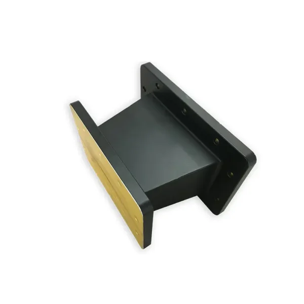
The quotation identifies both waveguide sections, both flange faces, the common operating band and the required mechanical envelope.
Adjacent or non-adjacent WR sizes, with flat or grooved flange combinations and model-dependent lengths.
View standard transitionsPublished models cover R14 to R900 interfaces, circular inside diameters and lengths from 20 to 920 mm.
View rectangular-to-circularPublished configurations cover 2.6 to 40 GHz with model-dependent shared bands and 50 to 180 mm lengths.
View ridge-to-rectangularPublished families cover model-dependent WRD interfaces from 3.5 to 18 GHz, with typical VSWR up to 1.15:1.
View double-ridge transitionsUse for mixed sizes, shapes, custom flange geometry, unusual clocking or a transition built into a larger assembly.
View special transitions
Specify the actual mating parts and the available space. Dolph can review a stand-alone transition or combine the transition with bends, twists, straight sections, flexible sections or end flanges.
Add power, envelope, finish, quantity and document requirements when available.
| Transition family | Published frequency | Published interface scope | Published VSWR reference | Published length reference | Published materials | Product data |
|---|---|---|---|---|---|---|
| Standard rectangular transition | 0.35–91.9 GHz | WR2300–WR12 catalog coverage | Selected entries 1.05:1 | 50–1000 mm by listed models | Aluminum and copper | Model table |
| Special waveguide transition | 0.35–91.9 GHz | Mixed size, shape or interface type | Published ≤1.04:1 in overlap bands | Defined by project | Aluminum 6061 or brass | Family data |
| Rectangular to circular | 1.30–112 GHz in listed models | R14–R900 with listed circular I.D. | ≤1.10:1 or ≤1.15:1 by model | 20–920 mm | Aluminum or copper | Model table |
| Double-ridge to rectangular | 2.6–40 GHz | WRD, UDR and UBR combinations | 1.06:1–1.15:1 by configuration | 50–180 mm examples | Aluminum | Family data |
| Double-ridge transition | 3.5–18 GHz | Model-dependent WRD families | Typical ≤1.15:1 | Confirm by model | Aluminum; custom options listed | Model data |
Published values are family or model references. The quotation and approved drawing define the final operating band, interfaces, dimensions, finish, test method and acceptance limits.
Published transition families list aluminum, copper, brass and oxygen-free copper depending on the product. Standard model notes list corrosion-protection treatment, flat-black paint and polished mating flanges. Other finishes and paint colors are available by request.

Prototype and production requirements are handled through the same interface, drawing and acceptance review.
Review both ports, operating band, electrical target, power, envelope, material, finish, quantity and required files.
Confirm waveguide sections, flange standards, mating faces, clocking and usable overlap between the two ports.
Define transition length, profile, bend or twist integration, mounting clearance and any cooling or pressure features.
Align model designation, drawing, material, finish, tolerances, file package and RF acceptance limits before release.
Use the agreed mix of CNC machining, turning, forming, bending, brazing, assembly, passivation or plating.
Complete agreed dimensional and RF checks, compile the required records and prepare the order for shipment.
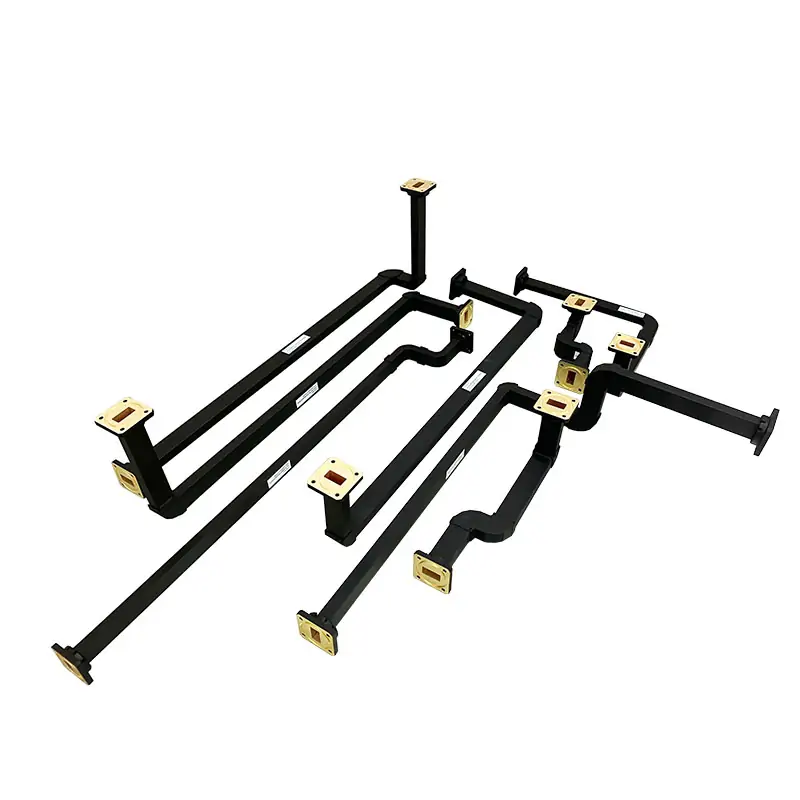
A dimensioned drawing is preferred. A clear sketch can start the review when it identifies both interfaces and the available space.
Dolph lists CNC machining, turning, waveguide forming and bending, brazing, assembly, passivation, plating and electroforming among its manufacturing capabilities.
Machined flange faces, transition bodies, circular interfaces and custom mounting geometry.
Rigid, preformed and multi-bend sections for assemblies that must follow a fixed equipment route.
Soldering and brazing support for copper, copper alloys and aluminum, including fully brazed custom assemblies.
Anodising, passivation, electrolytic and electroless plating, plus project-specific coating requirements.
Dolph lists vector and scalar measurement systems up to 100 GHz for component verification work.
Published support capabilities include high-power transmitters and waveguide calibration services.
Dolph lists antenna anechoic chamber work and EMI/EMS testing among its measurement services.
Published services include temperature and altitude, salt fog, humidity and other environmental checks.
Link the transition to the surrounding sections so flange orientation, total length and assembly access are checked together.
Dolph describes its business as a microwave component and antenna feed-system manufacturer.
Company informationThe certificate scope covers waveguide component design, manufacture and sale. The document states validity through August 7, 2026; confirm current status before order.
Review certificatePublished product tables include model-level frequency, VSWR, dimensions, interfaces, material, finish and file references.
Review model tableThe website states a one-year warranty from delivery against defective material and workmanship under its terms.
Review warranty statementDesign considerations for impedance matching, mechanical connection and thermal conditions.
Read articleChecks for measurement, flange selection, sealing, thermal expansion and mounting alignment.
Read articlePractical checks for flange surfaces, alignment, bolt tightening and post-installation VSWR testing.
Read articlePoints to confirm for continuous-wave power, peak power, breakdown limits and cooling.
Read articleFinal values depend on the exact two-port combination and approved configuration.
Yes. Provide both waveguide and flange designations. The usable operating band must fit the overlap of the two interfaces and the agreed transition design.
Yes. Dolph publishes custom assemblies that combine rigid sections, E-plane or H-plane bends, twists, flexible sections and end flanges.
Yes. Published models cover R14 through R900 entries, with listed circular inside diameters, aluminum or copper construction and model-specific lengths.
Send a dimensioned PDF, DWG or STEP file when available. A clear sketch can start the review if it identifies both ports, clocking and space limits.
State the required approval drawing, PDF, DWG, STEP, dimensional record and RF test record in the RFQ. The final document package is agreed in the quotation.
State the service environment, conductivity needs, weight limit, corrosion exposure and mating-flange treatment. Available choices depend on the transition family.
Provide average power, peak power, pulse width, duty cycle, pressure or gas condition and cooling requirements. Do not use frequency alone as the power specification.
Yes. Send the existing drawing, sample dimensions, interface details, operating band, acceptance limits and any known installation problem.

Include the operating band, electrical target, power, space limit, material, finish, document package, quantity and required date. Attach a drawing or sketch when available.