Dolph Microwave
Seamless Flexible Waveguide Assemblies
Use a seamless flexible section to reach a flange or route around limited space. Choose the size and length from the RF requirements, then check the bending route and pressure conditions.
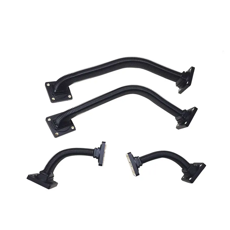
- Combined model coverage
- 1.13–50.1 GHz
- Bending directions
- E & H planes
- Listed maximum pressure
- 30 PSIG
Before you order
Specify the installed shape, not only the length
Routing and support
Show the flange faces, fixed supports and installed route on a sketch. Specify the minimum centerline bend radius required in each plane. For moving assemblies, add the motion range, frequency and required cycle life; flexibility for installation does not establish a repeated-motion rating.
Loss and average power
The catalogue lists 0.12 dB/m and 20 kW average power for WR650, compared with 2.7 dB/m and 0.05 kW for WR22. These are model-row values, not ratings for every length or shape. Confirm frequency, bend configuration, temperature and cooling conditions for the ordered assembly.
Core, jacket and temperature
The table lists Brass / BeCu cores and silicone jackets; the construction description also offers neoprene and lists −20°C to +100°C. Confirm the selected core, jacket, plating and the complete assembly’s temperature limits on the order drawing.
Position waveguide supports and hangers to carry the installed run without loading the flexible section at a flange. Include support positions in the routing drawing.
For the rest of your setup
Do the flange faces also need to twist?
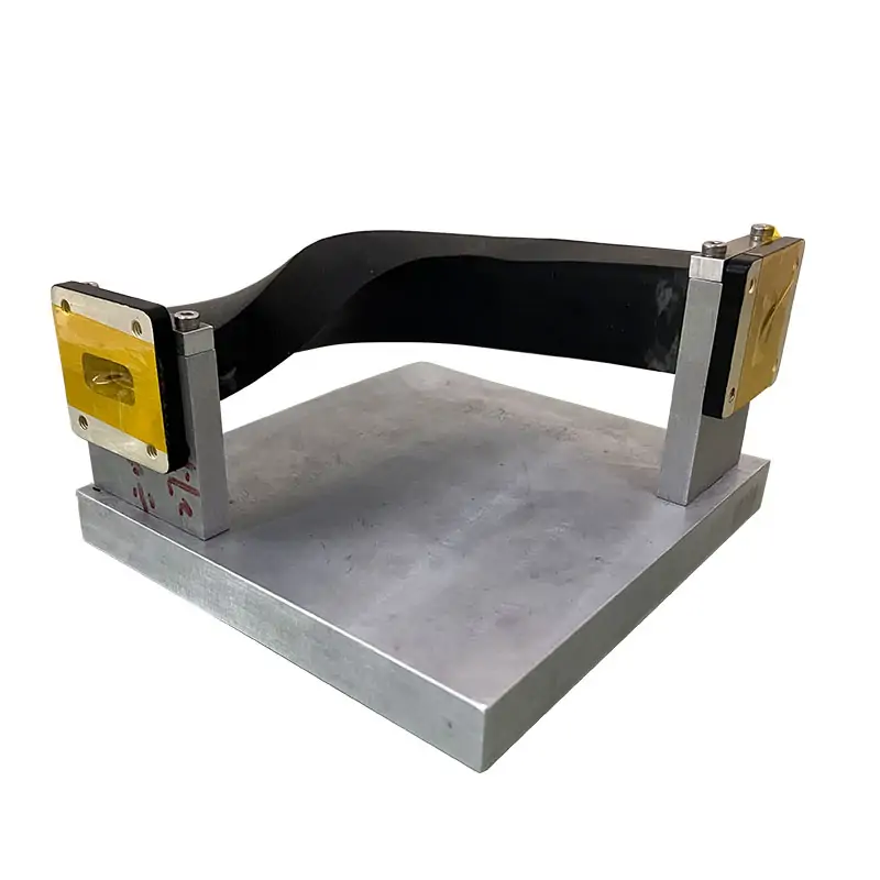
Bending in the E-plane or H-plane does not establish a torsion rating. If the ends need rotation relative to each other, compare the twistable range and specify the angle.
View twistable flexible waveguidesMIL-DTL-287 treats twistable and non-twistable flexible assemblies as separate classes.[1] This distinction supports specifying torsion separately; it does not certify these catalogue models to that specification.
Technical data
Specifications & dimensions
Swipe or scroll across the table to see all columns.
| MODEL | FREQ RANGE (GHz) | WG SIZE | VSWR | IL (dB/m) | AVG POWER (KW) | MAX. PRESSURE (PSIG) | FLANGES TYPE | CORE MATERIAL | JACKET TYPE | DATASHEET | ||
|---|---|---|---|---|---|---|---|---|---|---|---|---|
| COVER | GROOVED | |||||||||||
| DH-14WWEL… | 1.13-1.73 | WR650 | 1.1:1 | 0.12 | 20 | 30 | UDR14 | PDR14 | Brass / BeCu | Silicone | — | — |
| DH-22WWEL… | 1.72-2.61 | WR430 | 1.1:1 | 0.15 | 20 | 30 | UDR22 | PDR22 | Brass / BeCu | Silicone | — | — |
| DH-26WWEL… | 2.17-3.3 | WR340 | 1.1:1 | 0.15 | 20 | 30 | UDR26 | PDR26 | Brass / BeCu | Silicone | — | — |
| DH-32WWEL… | 2.6-3.95 | WR284 | 1.1:1 | 0.15 | 10 | 30 | UDR32 | PDR32 | Brass / BeCu | Silicone | — | — |
| DH-40WWEL… | 3.22-4.9 | WR229 | 1.1:1 | 0.17 | 8 | 30 | UDR40 | PDR40 | Brass / BeCu | Silicone | — | — |
| DH-48WWEL… | 3.94-5.99 | WR187 | 1.1:1 | 0.24 | 6.5 | 30 | UDR48 | PDR348 | Brass / BeCu | Silicone | — | — |
| DH-58WWEL… | 4.64-7.05 | WR159 | 1.1:1 | 0.22 | 6 | 30 | UDR58 | PDR58 | Brass / BeCu | Silicone | — | — |
| DH-70WWEL… | 5.38-8.17 | WR137 | 1.1:1 | 0.25 | 5 | 30 | UDR70 | PDR70 | Brass / BeCu | Silicone | — | — |
| DH-84WWEL… | 6.57-9.99 | WR112 | 1.1:1 | 0.3 | 4 | 30 | UDR84/UBR84 | PDR84/PBR84 | Brass / BeCu | Silicone | — | — |
| DH-100WWEL… | 8.2-12.5 | WR90 | 1.1:1 | 0.4 | 3 | 30 | UDR100/UBR100 | PDR100/PBR100 | Brass / BeCu | Silicone | — | — |
| DH-120WWEL… | 9.84-15 | WR75 | 1.15:1 | 0.5 | 1.5 | 30 | UBR120 | PBR120 | Brass / BeCu | Silicone | — | — |
| DH-140WWEL… | 11.9-18 | WR62 | 1.15:1 | 0.8 | 1 | 30 | UBR140 | PBR140 | Brass / BeCu | Silicone | — | — |
| DH-180WWEL… | 14.5-22 | WR51 | 1.15:1 | 1.1 | 0.5 | 30 | UBR180 | PBR180 | Brass / BeCu | Silicone | — | — |
| DH-220WWEL… | 17.6-26.7 | WR42 | 1.2:1 | 1.2 | 0.3 | 30 | UBR220 | PBR220 | Brass / BeCu | Silicone | — | — |
| DH-260WWEL… | 21.7-33 | WR34 | 1.25:1 | 1.5 | 0.2 | 30 | UBR260 | PBR260 | Brass / BeCu | Silicone | — | — |
| DH-320WWEL… | 26.3-40 | WR28 | 1.3:1 | 2 | 0.15 | 30 | UBR320 | PBR320 | Brass / BeCu | Silicone | — | — |
| DH-400WWEL… | 32.9-50.1 | WR22 | 1.3:1 | 2.7 | 0.05 | 30 | FUGP400/UG-383U/M | Brass / BeCu | Silicone | — | — | |
| Ordering example: DH-100WWEL300PMA 100 identifies WR90; WWEL identifies the seamless flexible family; 300 indicates a nominal 300 mm length. The existing key describes P as rectangular flat and M as rectangular grooved. Confirm both complete flange designations and the final material suffix on the approved drawing; the catalogue key does not consistently define the example’s final A. | ||||||||||||
| Note: Available Preformed bend and hybrid flexible waveguide assemblies. Length of Seamless Flexible Assemblies The standard recommended length for the various waveguide sizes. MM: 300, 500, 600, 900, 1000, 1200 and 1500. Other lengths may be available on request but may be subject to tooling and design charges. Accessories Hardware, fixing and clamping kit accessories are available for use with our flexible waveguide products. | ||||||||||||
Conditions to confirm with the model data
The frequency span of 1.13–50.1 GHz combines 17 model ranges; no single row covers that entire span. The table does not publish the length, bend state or temperature used for its RF and power ratings. Request acceptance limits for the ordered assembly and a measured insertion-loss/VSWR sweep at the agreed installed shape.
For a preliminary length calculation, the WR90 value of 0.4 dB/m gives 0.20 dB for 500 mm. This arithmetic excludes any additional flange, bend or mismatch effects and is not an assembly acceptance limit.
The listed 30 PSIG equals about 207 kPa gauge. Confirm working versus proof-test pressure, test medium, duration, allowable leakage and temperature; the table supplies no leak-rate or proof-test procedure.
The WR187 row lists PDR348, unlike the neighbouring size-code pattern. Confirm that flange designation from the mating drawing before ordering. Dashes in the PDF/STEP columns mean no model-specific download is linked here; request the current datasheet and dimensional file.
Materials & ordering options
Technical documents
Questions before ordering
Are other lengths available?
The original specification allows other lengths on request and notes possible tooling or design charges. Send the installed length, route and flange codes.
Can I specify preformed bends or fixing hardware?
The source lists preformed bends, hybrid flexible assemblies and hardware, fixing and clamping kits. Include these requirements in the enquiry.
Related products
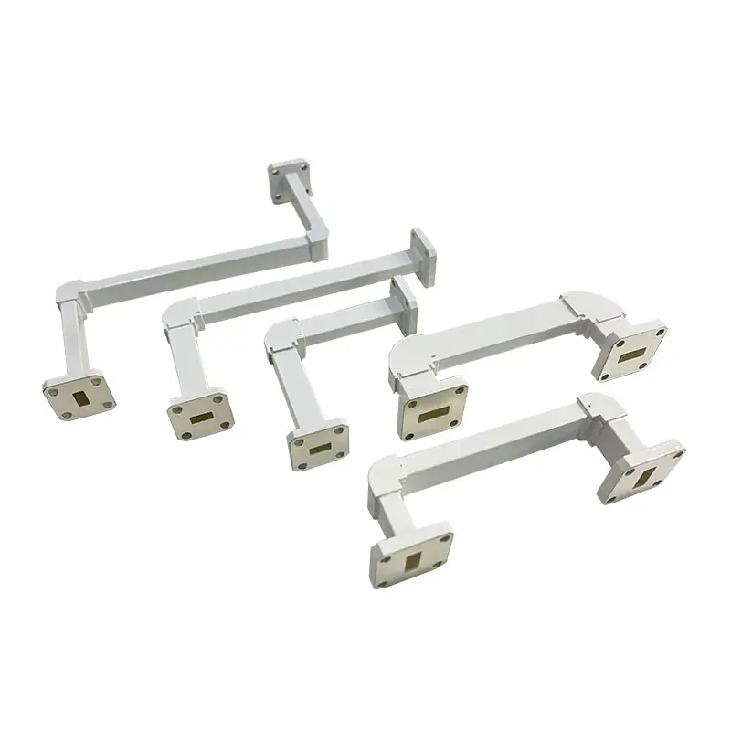
Waveguide Miter Bends
View productFor a fixed directional change in a waveguide run.
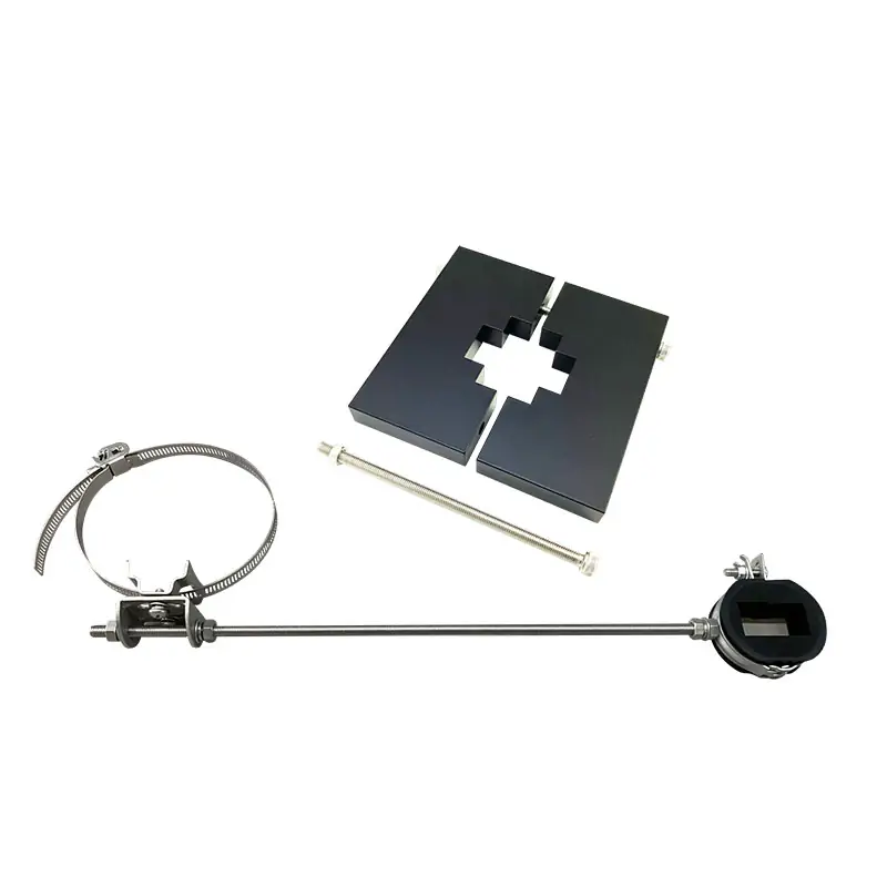
Waveguide Standoff and Hangers
View productFor positioning and support of the installed assembly.
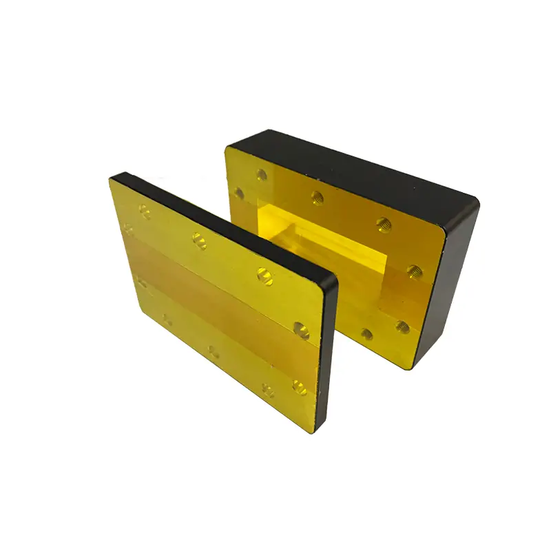
Waveguide Flange Standard EIA & IEC
View productTo match cover and grooved flange interfaces.
Tell us what you need
Have a model or drawing?
Send WR size, frequency, end-to-end length, a routing sketch, both flange codes, average power, pressure and temperature conditions.