Double-Ridged Waveguide · VNA Calibration
Double-Ridged Precision Waveguide Calibration Kits
For double-ridged waveguide VNA measurement setups from 0.84 to 40 GHz. Choose the kit by WRD size, full frequency range, coax connector and flange. The current model table keeps the adapter VSWR, termination, short, lambda-section dimensions, material, finish and drawing information together so you can check the complete interface before ordering.
Choose the complete interface
Frequency alone is not enough
Several WRD ranges overlap. Two kits can cover part of the same frequency range but still use a different waveguide opening, flange or coax connector. Match the whole setup, not only the GHz number.
Use the lowest and highest frequency you actually need to calibrate. Do not choose from the center frequency only.
Match the same double-ridged waveguide family used by the DUT, fixture and adjoining waveguide parts.
The current guide identifies N-Type, SMA-Type and 2.92 mm. The model and interface should be checked together.
Use the complete FPWRD designation in the table. A similar-looking flange name is not enough for a mechanical match.
If the mating interface is fixed, check the DWG or STEP file before the order is released.
Real hardware context
What the waveguide interface looks like in practice
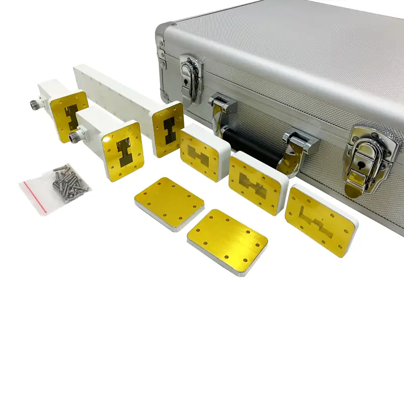
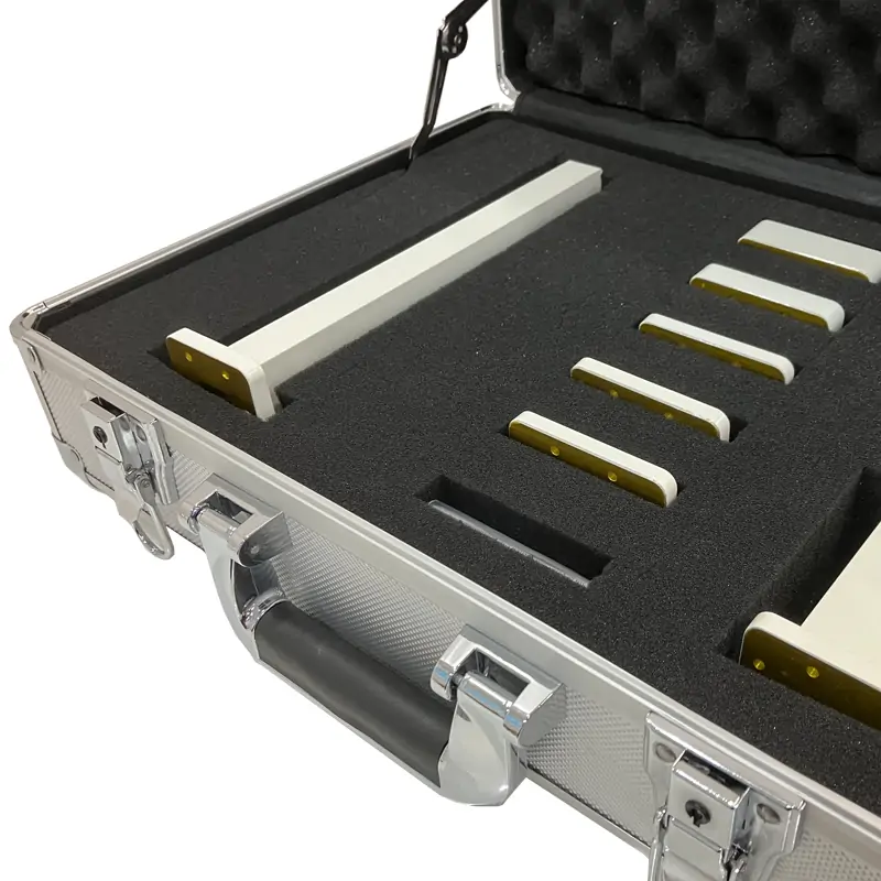
These are Dolph Microwave product and factory images from the same waveguide product family. They are included here to show the physical scale, flange styles and surrounding hardware rather than using generic stock graphics.


Published calibration-kit PDF
What is listed in the kit
The official Precision Waveguide Calibration Kits PDF lists the components below. Quantities and parameters are kept as published instead of being compressed into a general feature list.
The PDF is a broader calibration-kit document and also covers standard waveguide products. Use the current double-ridged model table further down this page for the exact WRD model values.
Before you place the order
These details are worth checking first
Most ordering mistakes on this type of part are interface mistakes. A quick check of the points below is more useful than adding more marketing claims.
Does the WRD size match?
A shared frequency range does not make two WRD sizes interchangeable. Use the same WRD family as the mating parts.
Is the flange code exact?
Compare the complete FPWRD code with the mating drawing. If the interface is project-controlled, send the drawing with the RFQ.
Is the connector the one you use?
The published guide uses N, SMA and 2.92 mm connector families. Confirm connector style together with the selected model.
Do you need the full band?
Choose a model that covers your complete start-to-stop range. Do not rely on a partial overlap between two model bands.
Do you need CAD before purchase?
DWG and STEP are listed for all current rows. Ask for the file before approval when envelope or mating dimensions are critical.
What records do you need?
Put required drawings, calibration data, dimensional records or RF test records in the RFQ so the deliverables are agreed before production.
Current product-page data
Double-ridged calibration kit model table
Every model-specific value below is retained from the current product page. Read across one complete row. Do not combine the frequency from one row with the flange, material or section dimensions from another.
| Model | Frequency Range (GHz) | WG Size | Adapters (VSWR) | Termination (VSWR) | Short (VSWR) | Waveguide Offsets THK. (mm) | Hardware (Screws/Nuts/Washers) |
Storage Case | Flanges Type | Material | Finish | RoHS & Reach | Drawing | 3D File | |||
|---|---|---|---|---|---|---|---|---|---|---|---|---|---|---|---|---|---|
| Female Connector | Male Connector | 1/8λ Section | 1/4λ Section | 3/8λ Section | |||||||||||||
| DH-84DRVNAWKN | 0.84-2.0 | WRD840 | 1.25:1 | 1.25:1 | 1.05 | 60 | 35.76 | 71.53 | 107.29 | 1 set | 1 | FPWRD840U24 | Al | Chromate/Painted | Comply | DWG | STEP |
| DH-150DRVNAWKN | 1.5-3.6 | WRD150 | 1.25:1 | 1.25:1 | 1.05 | 60 | 19.82 | 39.63 | 59.45 | 1 set | 1 | FPWRD150D24 | Al | Chromate/Painted | Comply | DWG | STEP |
| DH-200DRVNAWKN | 2.0-4.8 | WRD200 | 1.25:1 | 1.25:1 | 1.05 | 60 | 14.87 | 29.74 | 44.60 | 1 set | 1 | FPWRD200D24 | Al | Chromate/Painted | Comply | DWG | STEP |
| DH-250DRVNAWKN | 2.6-7.8 | WRD250 | 1.25:1 | 1.25:1 | 1.05 | 60 | 9.91 | 19.83 | 29.74 | 1 set | 1 | FPWRD250D30 | Al | Chromate/Painted | Comply | DWG | STEP |
| DH-350DRVNAWKN | 3.5-8.2 | WRD350 | 1.25:1 | 1.25:1 | 1.05 | 60 | 8.77 | 17.53 | 26.30 | 1 set | 1 | FPWRD350D24 | Al | Chromate/Painted | Comply | DWG | STEP |
| DH-475DRVNAWKN | 4.75-11.0 | WRD475 | 1.25:1 | 1.25:1 | 1.05 | 60 | 6.56 | 13.12 | 19.68 | 1 set | 1 | FPWRD475D24 | Al | Chromate/Painted | Comply | DWG | STEP |
| DH-500DRVNAWKS | 5.0-18.0 | WRD500 | 1.25:1 | 1.25:1 | 1.05 | 60 | 4.46 | 8.93 | 13.39 | 1 set | 1 | FPWRD500D36 | Al | Chromate/Painted | Comply | DWG | STEP |
| DH-580DRVNAWKS | 5.8-16.0 | WRD580 | 1.25:1 | 1.25:1 | 1.05 | 60 | 4.78 | 9.57 | 14.35 | 1 set | 1 | FPWRD580D28 | Al | Chromate/Painted | Comply | DWG | STEP |
| DH-650DRVNAWKS | 6.5-18.0 | WRD650 | 1.25:1 | 1.25:1 | 1.05 | 60 | 4.12 | 8.24 | 12.36 | 1 set | 1 | FPWRD650D28 | Al/Cu | Chromate/Painted | Comply | DWG | STEP |
| DH-750DRVNAWKS | 7.0-18.5 | WRD700 | 1.25:1 | 1.25:1 | 1.05 | 60 | 3.99 | 7.98 | 11.96 | 1 set | 1 | FPWRD700D26 | Al/Cu | Chromate/Painted | Comply | DWG | STEP |
| DH-700DRVNAWKS | 7.5-18.0 | WRD750 | 1.25:1 | 1.25:1 | 1.05 | 60 | 3.96 | 7.93 | 11.89 | 1 set | 1 | FPWRD750D24 | Al/Cu | Chromate/Painted | Comply | DWG | STEP |
| DH-1100DRVNAWKK | 11.0-26.5 | WRD110 | 1.25:1 | 1.25:1 | 1.05 | 60 | 2.69 | 5.38 | 8.07 | 1 set | 1 | FPWRD110C24 | Al/Cu | Chromate/Painted | Comply | DWG | STEP |
| DH-1800DRVNAWKK | 18.0-40.0 | WRD180 | 1.25:1 | 1.25:1 | 1.05 | 60 | 1.83 | 3.65 | 5.48 | 1 set | 1 | FPWRD180C24 | Al/Cu | Chromate/Painted | Comply | DWG | STEP |
Part-number guide shown on the current product page.
Read the part number before you quote it
The guide is useful for a quick check, but the current model table remains the safer place to confirm the exact frequency, WRD and flange combination.
Which family should you buy?
Double-ridged and standard waveguide kits are not the same product
This page: Double-ridged waveguide
Use this family when your system uses WRD interfaces. The current table covers WRD840 through WRD180 and published bands from 0.84 to 40 GHz.
- WRD waveguide interface
- N / SMA / 2.92 mm connector families in the published guide
- FPWRD flange codes in the current table
- Current model table lists 13 configurations
Standard rectangular waveguide kits
If the test path uses standard WR rectangular waveguide rather than WRD, use the separate standard-waveguide calibration-kit family instead of trying to adapt the values on this page.
- Separate WR-family model table
- Different flange and size designations
- Different connector options at higher bands
- View Standard Waveguide Precision Calibration Kits
Manufacturing and verification context
See the work behind the waveguide hardware
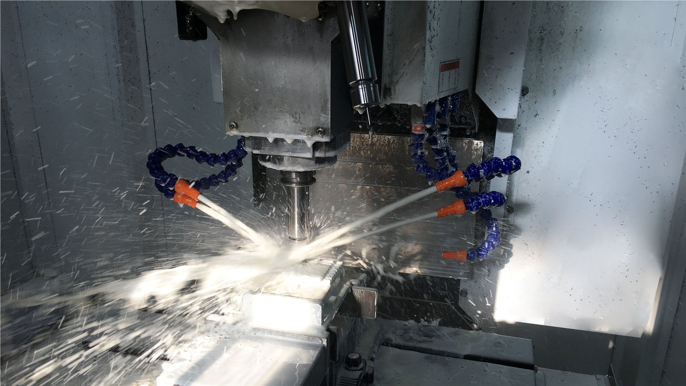
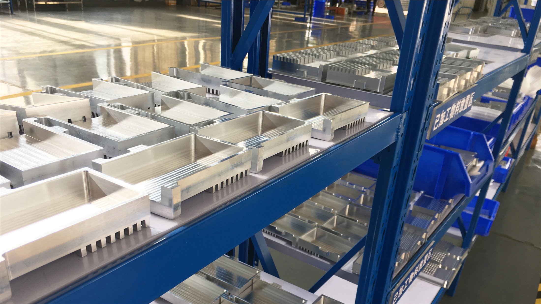
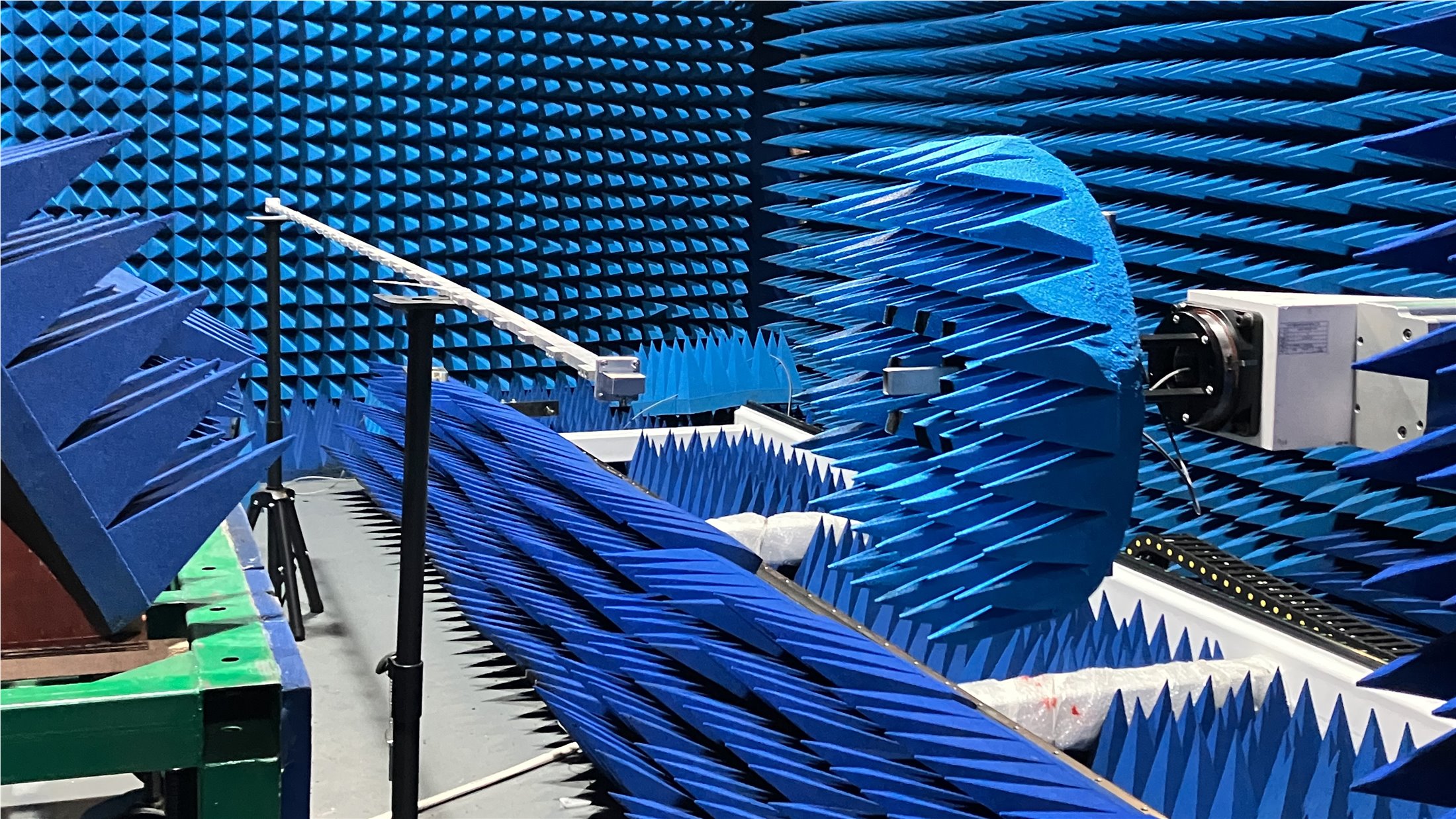
Dolph lists CNC milling and turning, waveguide forming and bending, soldering and brazing, plating and electroforming among its manufacturing capabilities. The site also publishes RF measurement capability up to 100 GHz. These factory images give buyers something concrete to check beyond a specification table.
What helps a technical buyer approve the order
Use the product data as an approval checklist
A buyer usually needs more than a model name. These are the practical points that make it easier to compare the quote with the test setup, drawing and purchasing requirement.
Electrical match
Keep the complete operating band and the adapter/termination values tied to one published model row.
Mechanical match
Check WRD size, FPWRD flange code and any critical mating dimensions before approval.
CAD handoff
DWG and STEP are listed for each current model. Use them when the available envelope is controlled.
Finish requirement
The current table lists Chromate/Painted. The product note says other finishes and paint colors can be requested.
Compliance field
The current model table marks RoHS & Reach as “Comply” for all 13 published rows.
Document scope
State any required calibration data, dimensional report or RF record in the RFQ instead of assuming it is included.
Technical references
Downloads and useful internal links
Official calibration-kit component list and product reference.
Use the flange reference when checking mating interface designations.
Browse matching WRD components around the calibration setup.
Useful when the requirement is the adapter only rather than a complete calibration kit.
Technical reading
Useful reading before setting up a waveguide measurement
These internal articles can help with the setup side. Use your VNA manufacturer’s procedure and the approved calibration-kit data as the final operating reference.
Waveguide Calibration: 5 Key Steps for Accurate RF Measurements
General setup points covering connections, frequency range, calibration standards and test documentation.
Read article →How to Calibrate Waveguide Feed Systems for Optimal Performance
A broader waveguide-system article for checking connections, alignment and measurement setup.
Read article →Questions buyers usually need answered
Precision waveguide calibration kit FAQ
What frequency range does the current double-ridged series cover?
The current product table starts at 0.84-2.0 GHz for DH-84DRVNAWKN / WRD840 and extends to 18.0-40.0 GHz for DH-1800DRVNAWKK / WRD180. Individual model bands overlap, so check frequency together with WRD and flange.
Can I select a kit only by GHz range?
No. Several models overlap in frequency. The WRD size, flange designation and coax connector are part of the interface and need to match the test setup.
Which connector families are shown in the part-number guide?
The current guide identifies N-Type, SMA-Type and 2.92 mm. Confirm the selected model and the exact mating connector requirement before order release.
What lambda sections are listed?
The current table gives model-specific thickness values for 1/8λ, 1/4λ and 3/8λ sections. The broader official kit PDF also lists one of each section in its kit contents.
Why does the PDF show VSWR≤1.03 for the matched termination while the current table shows 1.05?
They come from two different published Dolph references. The broader calibration-kit PDF lists WG Matched Termination as VSWR≤1.03, while the current online double-ridged table lists Termination (VSWR) as 1.05. For purchasing, confirm the value tied to the exact quoted model and approved documentation.
Are drawings available?
The current product table lists DWG and STEP for every published row. If dimensions or mating interfaces are critical, ask for the applicable file before approving the order.
A good RFQ should make the model obvious
Send the full frequency band, WRD size, connector, mating flange or drawing, quantity and the records you need with delivery. That gives engineering enough information to check the interface instead of guessing from frequency alone.