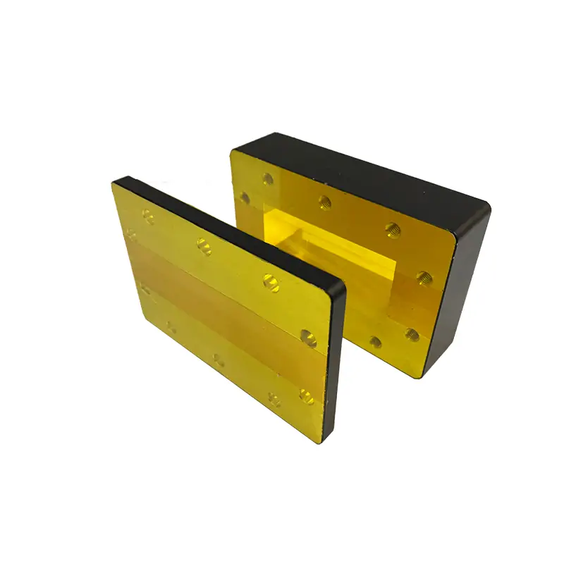
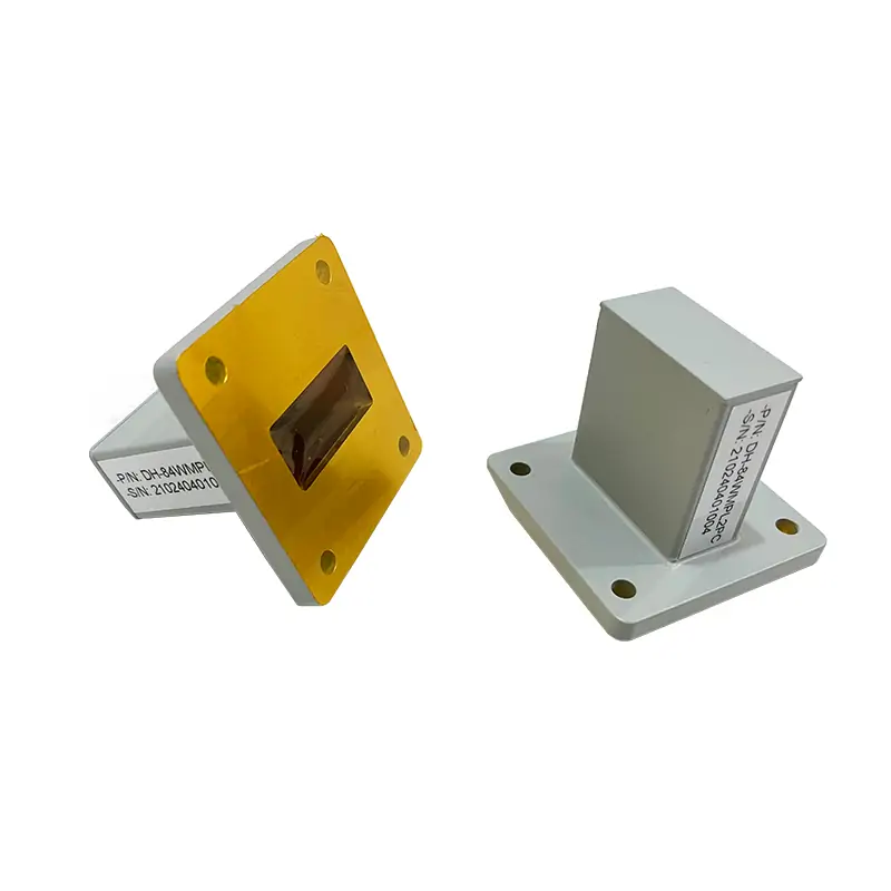
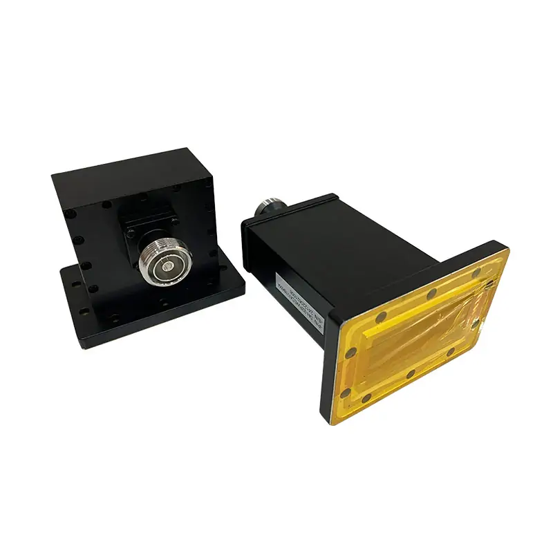
Choose the Correct WRD Load
Match the complete frequency band, WRD size, CW power and exact flange code to one published model. If the mating interface or envelope differs, send the drawing before ordering.
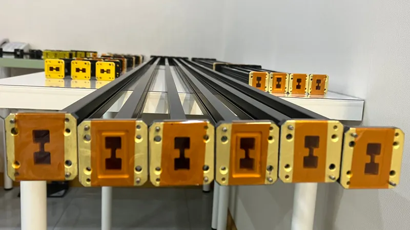
Full Published Model Data
Use one row for the full requirement. Do not mix a frequency range, power value or flange code from different models.
| MODEL | FREQ. RANGE (GHz) | WG SIZE | VSWR | AVG POWER CW (W) | FLANGES TYPE | LENGTH (mm) | INGRESS PROTECTION | MATERIAL | FINISH | DATASHEET | |
|---|---|---|---|---|---|---|---|---|---|---|---|
| COVER | GROOVED | ||||||||||
| DH-840DRWL… | 0.84-2.0 | WRD840 | 1.05:1 | 10 | FPWRD840U24 | FMWRD840U24 | 720 | IP65 | Al/Cu | Chromate/Painted | DWG STEP |
| DH-150DRWL… | 1.5-3.6 | WRD150 | 1.05:1 | 10 | FPWRD150D24 | FMWRD150D24 | 650 | IP65 | Al/Cu | Chromate/Painted | DWG STEP |
| DH-200DRWL… | 2.0-4.8 | WRD200 | 1.05:1 | 10 | FPWRD200D24 | FMWRD200D24 | 340 | IP65 | Al/Cu | Chromate/Painted | DWG STEP |
| DH-250DRWL… | 2.6-7.8 | WRD250 | 1.05:1 | 10 | FPWRD250D30 | FMWRD250D30 | 250 | IP65 | Al/Cu | Chromate/Painted | DWG STEP |
| DH-350DRWL… | 3.5-8.2 | WRD350 | 1.05:1 | 10 | FPWRD350D24 | FMWRD350D24 | 260 | IP65 | Al/Cu | Chromate/Painted | DWG STEP |
| DH-475DRWL… | 4.75-11.0 | WRD475 | 1.05:1 | 10 | FPWRD475D24 | FMWRD475D24 | 200 | IP65 | Al/Cu | Chromate/Painted | DWG STEP |
| DH-500DRWL… | 5.0-18.0 | WRD500 | 1.05:1 | 5 | FPWRD500D36 | FMWRD500D36 | 210 | IP65 | Al/Cu | Chromate/Painted | DWG STEP |
| DH-580DRWL… | 5.8-16.0 | WRD580 | 1.05:1 | 5 | FPWRD580D28 | FMWRD580D28 | 210 | IP65 | Al/Cu | Chromate/Painted | DWG STEP |
| DH-650DRWL… | 6.5-18.0 | WRD650 | 1.05:1 | 5 | FPWRD650D28 | FMWRD650D28 | 102 | IP65 | Al/Cu | Chromate/Painted | DWG STEP |
| DH-700DRWL… | 7.0-18.5 | WRD700 | 1.05:1 | 5 | FPWRD700D26 | FMWRD700D26 | 140 | IP65 | Al/Cu | Chromate/Painted | DWG STEP |
| DH-750DRWL… | 7.5-18.0 | WRD750 | 1.05:1 | 5 | FPWRD750D24 | FMWRD750D24 | 140 | IP65 | Al/Cu | Chromate/Painted | DWG STEP |
| DH-110DRWL… | 11.0-26.5 | WRD110 | 1.05:1 | 5 | FPWRD110C24 | FMWRD110C24 | 150 | IP65 | Al/Cu | Chromate/Painted | DWG STEP |
| DH-180DRWL… | 18.0-40.0 | WRD180 | 1.05:1 | 5 | FPWRD180C24 | FMWRD180C24 | 109 | IP65 | Al/Cu | Chromate/Painted | DWG STEP |
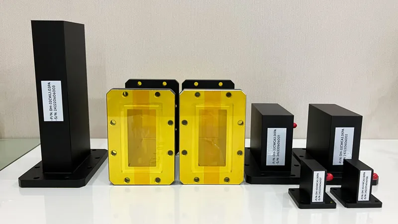
Part Number and Finish Details
All Dolph-MW models include Surtec/corrosion protection treatment and are painted flat black. Flanges are unplated, polished and Surtec. Other finishes and paint colors are available upon request.
The low-power termination family uses precision conical load elements. For a mating-interface check, send the flange drawing or use Dolph’s Waveguide Flange Size Guide.
Send Mating-Flange DrawingBuilt and Checked in Dolph’s Xi’an Factory
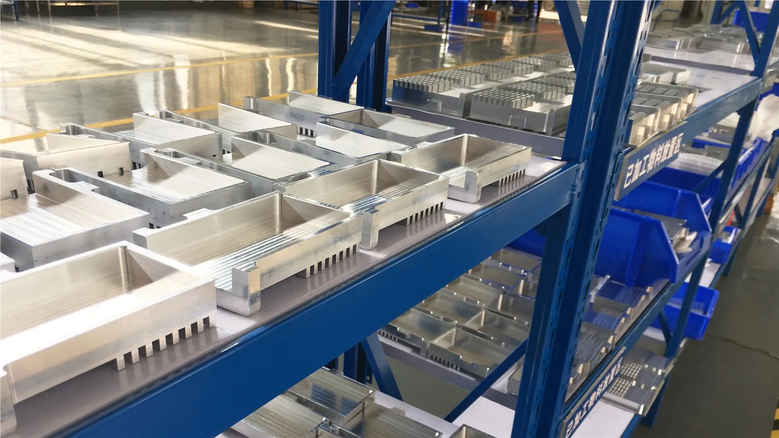
Dolph lists CNC machining and turning, waveguide forming and bending, soldering and brazing, electrolytic/electroless plating and electroforming among its manufacturing capabilities. Its published RF measurement capability reaches 100 GHz.
What to Send for a Firm Model Check
The published table covers CW power. Add pulse data whenever the load will see pulsed operation.
Operating band
Minimum and maximum frequency, not only the center frequency.
WRD and flange
WRD size plus the complete cover or grooved flange designation.
Power condition
CW average power; add peak power, pulse width and duty cycle when applicable.
Available envelope
Maximum length, mounting limits and mating-part dimensions.
Material and finish
Confirm Al/Cu requirement and any finish that differs from the published configuration.
Quantity and documents
Order quantity plus required drawing, dimensional or RF test records.
Manufacturing and Verification Support
Dolph’s current site lists waveguide manufacturing since 2001, RF measurement up to 100 GHz and a one-year product warranty against defective material and workmanship from delivery, subject to the published warranty terms.
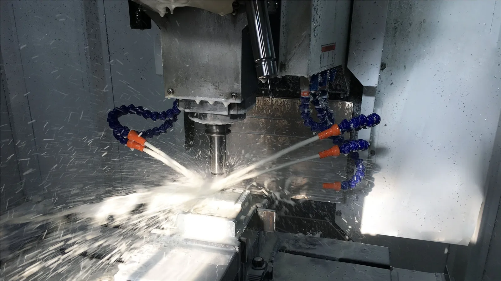
Machining and fabrication
CNC milling and turning, waveguide forming and bending, soldering and brazing are listed among the factory capabilities.
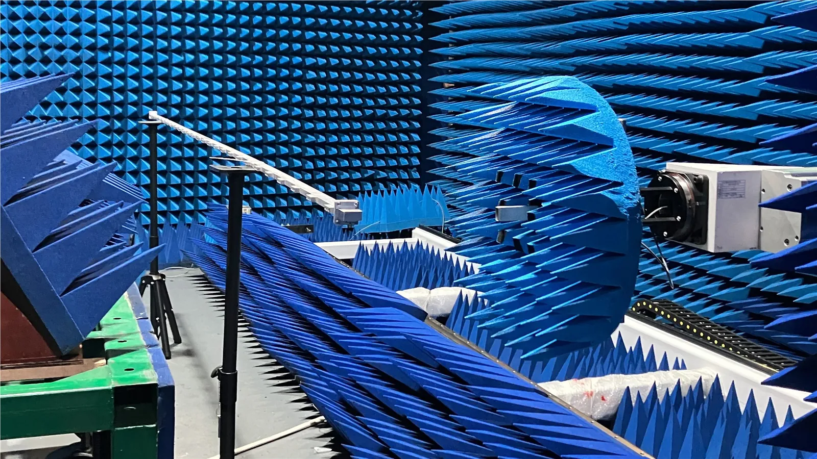
RF measurement
Published laboratory capability includes vector and scalar RF systems up to 100 GHz, plus antenna anechoic chambers.
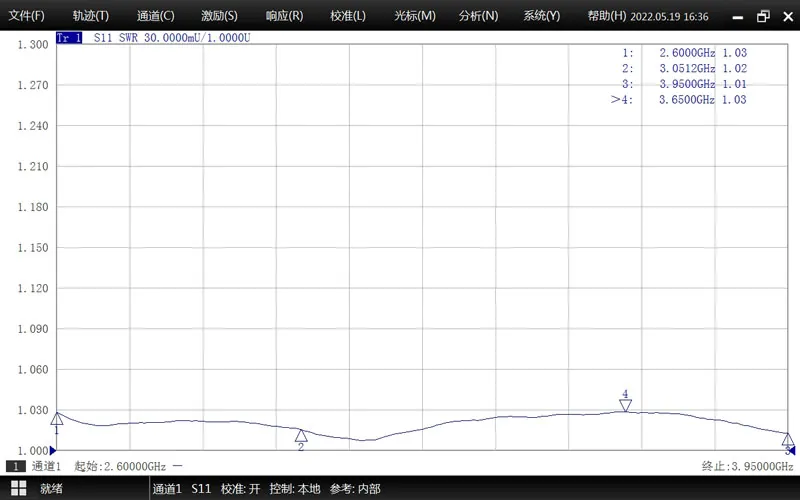
Order documentation
Define the required dimensional, RF or inspection records in the RFQ so the deliverables are confirmed before production.
If This Series Is Not the Right Fit
Use the load family that matches the required power, size and interface instead of applying this 5–10 W data outside its published range.
Send the Specs Needed for Quotation
Send the full operating band, WRD size, flange code, CW and pulse conditions, envelope limit, material/finish requirement, quantity and required inspection records. Dolph can confirm the closest published model or review a modified interface.
Technical Downloads
Use the flange reference to confirm interface designations. The high-power termination file is retained for comparison with higher-power load requirements.