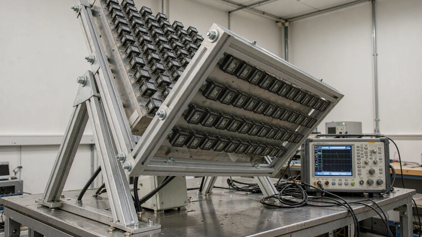
For a fixed site using a geostationary satellite, start with a fixed parabolic dish. For broadband while moving, or a directional link to LEO/MEO satellites, use an operator-approved electronically steered panel or a mechanically tracking dish. Large gateways often use dual-reflector dishes; handheld and low-rate services may use compact patch, helical, or omnidirectional antennas. The right choice depends on the service first, then motion, required link performance, and installation limits—not the antenna shape alone.
Table of Contents
Five Fit Decisions
- Separate site motion from satellite motion. A fixed GEO site can retain one alignment. A fixed LEO/MEO site may still need tracking; a moving platform also needs motion compensation for a narrow-beam link. Broad-beam low-rate terminals do not necessarily need continuous antenna steering.
- Identify the orbit. Geostationary satellites orbit above the equator at about 35,786 km and appear stationary to a ground observer. NASA places LEO at approximately 160–2,000 km and MEO at approximately 2,000–35,500 km. [1] Geostationary orbit is a special case of geosynchronous orbit; an inclined geosynchronous satellite does not stay at a fixed point in the sky. [2]
- Use exact operating frequencies. ESA lists broad letter-band ranges including C at 4–8 GHz, Ku at 12–18 GHz, and Ka at 26–40 GHz. These names are not substitutes for the service’s licensed receive and transmit ranges. Higher-frequency services typically offer wider bandwidth but are more susceptible to rain fade. [3] Use site rainfall, elevation angle, frequency, and polarization with an Earth-space propagation method such as ITU-R P.618-14 to estimate attenuation and the required fade margin. [4]
- Size for the link budget. Compare warranted receive performance, transmit performance, and beamwidth at the actual operating frequencies. The calculated examples below show how diameter and frequency affect gain; they are not product specifications.
- Check installation and interference limits. Include height, weight, power, cooling, wind loading, and mounting constraints. In the US, 47 CFR 25.209 sets earth-station antenna performance requirements that depend on the applicable band, polarization, and angular region; one envelope term is 29 − 25 log10(θ), with θ in degrees. It is not a universal mask for every antenna. [5]
Antenna Types Compared
Fixed parabolic dish
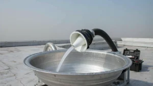
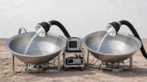
A fixed parabolic dish fits stationary GEO television, broadband, and enterprise links. An offset-fed design keeps the feed out of the main aperture. Select its diameter from the operator’s approved options and the site link budget, rather than assuming every home or VSAT link needs the same size. The mount must retain alignment under the specified environmental conditions.
Dual-reflector dish
Cassegrain and Gregorian layouts use a sub-reflector and are candidates for gateways and teleports requiring high gain and carefully controlled patterns. Dolph’s catalogue includes an 11.3 m earth-station antenna within its SATCOM antenna range. Diameter and reflector layout alone do not establish noise performance, sidelobe compliance, or suitability for a particular operator.
VSAT system
VSAT—very small aperture terminal—is a terminal class, not a separate reflector shape. A two-way installation needs an antenna, compatible feed, mount, transmit and receive RF equipment, and modem. For a stationary GEO service, a fixed dish is a natural starting point. Confirm the complete terminal configuration with the operator, including frequencies and polarization, before comparing aperture sizes.
Electronically steered flat panel
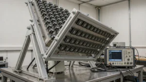
An electronically steered panel changes beam direction without rotating the whole antenna. It fits applications where profile, retargeting, or motion compensation matter, provided the network supports that terminal. Compare warranted equivalent isotropically radiated power (EIRP) and receive gain-to-noise-temperature ratio (G/T) across the required scan range, not just broadside gain. Include power draw, cooling, obstructions, and radome losses.
Mechanically tracking and stabilized dishes
A mechanically tracking reflector follows a moving satellite; a stabilized installation also compensates for platform motion. Those are distinct requirements. For fixed-site non-GEO work, X/Y-axis LEO/MEO tracking antennas are one configuration to investigate. A ship or aircraft needs an installation specifically rated for its motion environment. Confirm tracking rate, pointing accuracy, acquisition, and network handover behavior separately.
Horn feed and reference
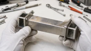
Horns illuminate reflectors and serve as test sources or standard-gain references. For the broadband ground-terminal applications discussed here, a horn is normally a feed or measurement component rather than an alternative to the complete dish or panel. Whether any antenna can close a particular satellite link remains a link-budget question.
Compact low-rate antennas
Compact patches, helices, and omnidirectional antennas can suit handheld or low-rate services when their coverage and polarization match the network. Directional helices and Yagis can provide more gain, but may need pointing or tracking; they should not all be treated as broad-beam antennas. Choose the pattern to suit the link’s pointing constraints, rather than grouping every portable antenna under one rule.
Application Match
Find your application in the left column, then read across for the fit and the reason. If two rows seem to fit, the orbit and motion rows decide before size does.
| Application | Usually the right fit | Why |
|---|---|---|
| Fixed GEO television or home broadband | Operator-compatible fixed dish | Stationary geometry permits fixed pointing; link budget and availability target set size |
| Fixed GEO enterprise VSAT | Approved dish, RF chain, and modem | Two-way service requires a compatible complete terminal, not just a reflector |
| Large gateway, teleport, or earth station | Large dual-reflector dish on solid foundation | High gain, low noise, sidelobes controlled toward adjacent satellites |
| Broadband while a ship, aircraft, or vehicle is moving | Motion-rated stabilized dish or electronically steered panel | Maintains a directional beam despite platform motion; network approval still applies |
| Directional LEO/MEO broadband at a fixed or moving site | Network-supported electronic or mechanical tracking terminal | Satellite motion requires beam management; the antenna and network must handle acquisition and handover |
| News, rescue, or field operation after stopping | Driveaway SNG antenna or quick-deploy dish | Transport, stop, deploy, and acquire; driveaway does not establish communication while driving |
| Laboratory, range, or feed development | Standard-gain horn as feed or reference | Known pattern and gain for measurement or dish illumination |
| Handheld or low-rate service | Network-compatible compact patch, helical, or omni | Coverage, polarization, and link budget determine whether rough pointing is acceptable |
Orbit and Tracking
A stationary building does not imply a stationary beam: a directional LEO/MEO terminal must follow the satellite even when its mount never moves geographically. Conversely, a vehicle used only after parking may use a deployable GEO dish rather than a communications-on-the-move system. Dolph’s driveaway product description explicitly distinguishes deployment after transport from operation while driving.
Free-space basic transmission loss between isotropic antennas is Lbf = 20 log10(4πd/λ), with distance d and wavelength λ in the same units. [6] For a calculated 12 GHz comparison, assume a satellite directly overhead: the path is about 35,786 km for GEO and 550 km for a hypothetical LEO satellite at that altitude. Losses are approximately 205.1 and 168.8 dB, a 36.3 dB difference. These are idealized overhead paths, not general slant ranges; lower-elevation paths are longer. Rain, atmosphere, antenna gains, and network performance are excluded.
Band, Size, Gain
Wavelength follows λ = c / f, with c = 299,792,458 m/s. These examples provide inputs to gain and beamwidth calculations; they are not licensed service allocations.
| Band example | Frequency | Wavelength |
|---|---|---|
| L-band | 1.5 GHz | about 200 mm |
| S-band | 2.5 GHz | about 120 mm |
| C-band | 4 GHz | about 75 mm |
| X-band | 10 GHz | about 30 mm |
| Ku-band | 12 GHz | about 25 mm |
| Ku-band uplink | 14 GHz | about 21 mm |
| Ka-band | 30 GHz | about 10 mm |
For a circular aperture, the model is G = η(πD/λ)² in linear units, or 10 log10(G) in dBi. NASA’s reflector analysis gives the equivalent relationship G = η × 4πA/λ²; substituting the circular area A = πD²/4 gives this expression. [7] The following calculations assume aperture efficiency η = 0.6 at every listed frequency. They do not include additional downstream feeder, mismatch, radome, or pointing losses. Real efficiency and the measurement reference plane must be established for the selected antenna.
| Dish | Frequency | Wavelength | Calculated gain, η = 0.6 |
|---|---|---|---|
| 0.6 m | 12 GHz, Ku-band | 25.0 mm | about 35.3 dBi |
| 0.9 m | 12 GHz, Ku-band | 25.0 mm | about 38.9 dBi |
| 1.2 m | 12 GHz, Ku-band | 25.0 mm | about 41.4 dBi |
| 2.4 m | 12 GHz, Ku-band | 25.0 mm | about 47.4 dBi |
| 1.2 m | 4 GHz, C-band | 75.0 mm | about 31.8 dBi |
| 1.2 m | 30 GHz, Ka-band | 10.0 mm | about 49.3 dBi |
As a sensitivity calculation—not a claimed production range—a 1.2 m dish at 12 GHz gives about 41.0 dBi at η = 0.55 and 42.0 dBi at η = 0.70. Ask which losses a supplier’s efficiency or gain figure already includes so that the link budget does not count them twice.
For calculated gain, request the efficiency assumption. For measured gain, request the test frequency, reference plane, and measurement conditions.
At the same frequency and efficiency, doubling diameter adds approximately 6.0 dB of gain. It also approximately halves beamwidth, so the mount and pointing system must support a narrower beam. Surface accuracy must be assessed against operating wavelength and the allowable efficiency loss, not diameter alone.
For an illustrative dish beamwidth estimate, use 70λ/D degrees, with λ and D in the same units. The coefficient already yields degrees. It gives approximately 1.5° for a 1.2 m dish at 12 GHz, 0.7° for 2.4 m at 12 GHz, and 0.6° for 1.2 m at 30 GHz. Actual half-power beamwidth depends on illumination and antenna design. Estimate site attenuation separately with ITU-R P.618-14; beamwidth is not a rain-margin calculation. [4]
Gain, Noise, Pointing
G/T expresses receive gain relative to system noise temperature, usually in dB/K. EIRP combines transmitter power and antenna gain, with losses referred to a consistent point. At 12 GHz and equal efficiency, a 1.2 m dish needs approximately four times the transmit power of a 2.4 m dish to produce the same EIRP, if all other losses are equal. Moving to the larger dish reverses that trade-off; it does not require four times the power.
For an idealized flat aperture, projected area scales as cos θ away from broadside. The calculated area-only loss −10 log10(cos θ) is about 1.5 dB at 45° and 3.0 dB at 60°. This is a geometric illustration, not a prediction of a particular panel’s scan performance. Element patterns, coupling, mismatch, polarization, and radome effects require actual EIRP and G/T curves across scan.
Beyond raw gain, neighboring satellites impose sidelobe envelopes, and the US earth-station rule cited above gives one enforceable example. [5] ITU-R S.465-6 gives the companion international reference pattern for coordination and interference assessment from 2 to 31 GHz. [8]
Mistakes
- A larger dish can lose its expected advantage if mount deflection or pointing error consumes the extra link margin. Check those errors before reusing the old mount.
- Panel thickness says little; panels of equal size differ in EIRP across scan, handover behavior, modem pairing, and power draw.
- Motorized acquisition is not proof of in-motion stabilization. A driveaway terminal that acquires GEO after parking is not automatically suitable for transmitting while the vehicle moves.
- Tracking can be unnecessary at a stationary GEO site, but remains useful or necessary for directional non-GEO links from the same site.
- Feed or waveguide loss before the receiver can degrade G/T; transmit-path loss reduces radiated power. Establish the RF reference planes before comparing complete terminals.
- An unapproved terminal can fail on frequency use, EIRP density, sidelobe behavior, or certification; the approved list comes before gain comparison. Off-axis EIRP-density envelopes for FSS earth stations in the covered bands are specified in 47 CFR 25.218. [9]
Worked Selection Scenarios
Parked emergency vehicle or broadband on the move?
Consider an emergency team that needs a link only after parking. A driveaway or flyaway GEO dish is a candidate: compare deployment clearance, roof or ground support, power, acquisition, and the approved RF chain. If the requirement changes to broadband while driving, reopen the selection around a motion-rated terminal. The driveaway label and automatic acquisition alone do not satisfy that new requirement. This is a selection scenario, not a reported customer deployment.
Same dish size, different pointing budget
Using the calculated 1.2 m examples above, a 0.3° pointing error is about one-fifth of the estimated 12 GHz beamwidth, but about one-half of the 30 GHz beamwidth. A mount acceptable for the first design therefore cannot be accepted for the second without checking its error budget and the measured antenna pattern. Those fractions compare angle with beamwidth; they are not calculated pointing losses in dB, and the examples are not field-test results.
Specification Checklist
A useful request specifies the satellite service, site location, exact receive and transmit ranges, polarization, data-rate and availability targets, whether operation is parked or in motion, mounting limits, and the required RF chain. A reflector diameter alone cannot define that configuration.
- Which satellite system and orbit is this terminal approved for?
- What are warranted EIRP and G/T, over which band and scan or tracking range?
- How does it acquire and hand over satellites, and how long does traffic pause?
- What are pointing accuracy, stabilization range, power, cooling, weight, and mounting envelope?
- What sidelobe, EIRP-density, and certification limits does it meet?
If the answer is only a broadside gain number or a panel thickness, ask for the sweep data, scan plots, and test conditions.
Choose the simplest operator-supported antenna that meets the link budget over the full operating range. That may be a fixed GEO dish, a parked deployable terminal, a stabilized or tracking broadband terminal, a gateway reflector, or a compact low-rate antenna. Final selection depends on documented performance and service compatibility, not a single gain figure.
Describe your application — orbit, frequency band, and mounting limits — to receive a configuration review for the terminal options above.
Request a Configuration ReviewReferences
- NASA Earthdata, Orbits. https://www.earthdata.nasa.gov/learn/earth-observation-data-basics/orbits
- European Space Agency, Types of orbits. https://www.esa.int/Enabling_Support/Space_Transportation/Types_of_orbits
- European Space Agency, Satellite frequency bands. https://www.esa.int/Applications/Connectivity_and_secure_communications/Satellite_frequency_bands
- Recommendation ITU-R P.618-14 (08/2023), Propagation data and prediction methods required for the design of Earth-space telecommunication systems. https://www.itu.int/dms_pubrec/itu-r/rec/p/R-REC-P.618-14-202308-I!!PDF-E.pdf
- 47 CFR 25.209, Earth station antenna performance standards, Federal Communications Commission, eCFR. https://www.ecfr.gov/current/title-47/chapter-I/subchapter-B/part-25/subpart-C/section-25.209
- Recommendation ITU-R P.525-5 (11/2024), Calculation of free-space attenuation. https://www.itu.int/dms_pubrec/itu-r/rec/p/R-REC-P.525-5-202411-I!!PDF-E.pdf
- NASA/TM—2011-217110, The Effect of Boundary Support and Reflector Dimensions on Inflatable Parabolic Antenna Performance, Equation (10). https://ntrs.nasa.gov/api/citations/20110023748/downloads/20110023748.pdf
- Recommendation ITU-R S.465-6 (01/2010), Reference radiation pattern of earth station antennas in the fixed-satellite service for use in coordination and interference assessment in the frequency range from 2 to 31 GHz. https://www.itu.int/rec/R-REC-S.465-6-201001-I/en
- 47 CFR 25.218, Off-axis EIRP density envelopes for FSS earth stations transmitting in certain frequency bands, Federal Communications Commission, eCFR. https://www.ecfr.gov/current/title-47/chapter-I/subchapter-B/part-25/subpart-C/section-25.218