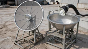
Yes, sometimes. A Ku-band dish reflector can be reused for Ka-band if its surface accuracy, feed geometry, and mount meet the target service requirements. Ku-only RF components need replacement; the modem needs a compatibility check, not an automatic replacement. For a small TV dish intended for two-way Ka-band broadband, an operator-approved Ka-band antenna system is the safer starting point than a custom conversion.
First separate two different projects: receiving a Ka-band signal and joining a two-way broadband network. Receive-only work needs a suitable reflector, feed, receiver, and signal coverage. A transmitting terminal also needs an accepted RF chain, network compatibility, and the applicable operating authorization. A reflector that works electrically is not, by itself, an approved broadband terminal.
Table of Contents
Why a Direct Swap Fails
The regulated U.S. FSS slices for the two bands do not overlap [1]. As a letter-band label, Ku covers roughly 12–18 GHz and Ka covers roughly 26–40 GHz [2]. In U.S. fixed-satellite service, conventional Ku uses 14.0–14.5 GHz up and 11.7–12.2 GHz down, while conventional Ka-band uses 28.35–28.6 and 29.25–30.0 GHz up with 18.3–18.8 and 19.7–20.2 GHz down [1]. Equipment specified only for those Ku-band frequencies is not suitable for the corresponding Ka-band frequencies. The letter-band labels are broad categories, not a complete terminal frequency plan; verify the actual service frequencies and national rules.
- Wavelength and tolerance. At 12 GHz the wavelength is about 25 mm. At 30 GHz it is about 10 mm (λ = c/f, with c = 299,792,458 m/s). For the same effective reflector error, the phase error at 30 GHz is 2.5 times that at 12 GHz. These are illustrative reference frequencies, not a comparison of Ku and Ka uplinks.
- Gain and beamwidth. Higher frequency raises gain and narrows the beam. On a 1.2 m dish the beam drops from about 1.46° to about 0.58° (illustrative values in the table below). An alignment error that stays inside the Ku-band beam can use up much of the Ka-band beam.
- Rain fade. Ka-band rain fade planning uses the ITU-R P.618 prediction methods with P.838 coefficients [3][4].
| Item | Ku-band (typical FSS) | Ka-band (typical FSS) |
|---|---|---|
| Letter-band range | About 12–18 GHz [2] | About 26–40 GHz [2] |
| U.S. conventional downlink | 11.7–12.2 GHz [1] | 18.3–18.8, 19.7–20.2 GHz [1] |
| U.S. conventional uplink | 14.0–14.5 GHz [1] | 28.35–28.6, 29.25–30.0 GHz [1] |
| Typical terminal character | TV, VSAT, mobile links [2] | High-throughput broadband, backhaul [2] |
| Service slice | Frequency | Wavelength |
|---|---|---|
| Ku downlink (conventional) | 11.7–12.2 GHz | 25.6–24.6 mm |
| Ku uplink (conventional) | 14.0–14.5 GHz | 21.4–20.7 mm |
| Ka downlink (conventional) | 18.3–18.8, 19.7–20.2 GHz | 16.4–15.9, 15.2–14.8 mm |
| Ka uplink (conventional) | 28.35–28.6, 29.25–30.0 GHz | 10.6–10.5, 10.2–10.0 mm |
Can the Reflector and Mount Stay?
The reflector and supporting structure are the main reuse candidates. Start with the actual operating frequency and allowable loss, rather than deciding from dish diameter or appearance alone.
- Reflector. A reflector needs verified surface accuracy and a feed that illuminates its geometry correctly. Dents, panel misalignment, and distortion need investigation. Missing surface data means reuse is unverified, not physically impossible: obtain manufacturer data or suitable measurements before committing to conversion.
- Mount and pedestal. Reuse needs measured backlash, wind deflection, and adjustment resolution that fit the Ka-band beam (see the gain and beamwidth table below). Check them against the manufacturer’s pointing specification. The mount must also carry the weight of the new feed and electronics.
- Civil works. Foundations, conduits, and shelter space may remain, subject to the new equipment loads, cable requirements, and site condition. Changing RF band does not alone establish that the existing infrastructure is adequate.
What Has to Be Replaced?
Separate components that handle the satellite RF band from equipment whose reuse depends on interface and network compatibility. Check specifications for each item instead of replacing everything by default.
Feed and Waveguide
Check the rated frequency range of the feed horn, waveguide, filters, and diplexer. A Ku-only assembly is not a Ka-band conversion kit. Use a Ka-capable feed with the correct illumination, phase-center position, polarization, and isolation for the reflector. Where the design uses an orthomode transducer, verify its full operating bands too. An existing multiband assembly is a different case: check its documented Ka capability and test the installed path for loss and mismatch.
Receive and Transmit Electronics
A Ku-only low-noise block downconverter (LNB) needs replacement for Ka reception. A two-way system also needs a Ka-capable block upconverter (BUC), power amplifier, and filtering matched to the operator’s frequency plan. Receive-only work does not require a BUC or transmit power amplifier. Check local-oscillator settings, intermediate-frequency interfaces, power supplies, and control connections before selecting replacements.
Modem and Service
The RF band alone does not determine whether a modem must be replaced. DVB-S2X, for example, addresses forward links using Adaptive Coding and Modulation and describes applications in both Ku and Ka bands [5]. Ask the target operator to confirm the modem model, intermediate-frequency range, waveform, symbol rates, software, and network provisioning. Reuse is an option only if those checks pass; support for the same standard alone is not network approval. Service migration and commissioning must be agreed with the operator.
Pointing and Weather Protection
Verify fixed-dish alignment and mobile-terminal tracking against the operator’s pointing-error allowance, including wind and mechanical backlash. Ka-band is more susceptible to rain fade [2]. Calculate the site-specific propagation margin using the ITU methods cited above. Dish heating does not remove attenuation caused by rain along the atmospheric path; assess any surface-weather protection separately from the rain-fade budget.
The table uses c = 299,792,458 m/s, λ = c/f, and an assumed 60% aperture efficiency for gain: G = η(πD/λ)², converted to dBi. Half-power beamwidth is estimated separately as 70λ/D degrees, with λ and D in the same units. That beamwidth approximation depends on illumination; it is not determined by the efficiency assumption. These are calculated examples before additional surface or pointing losses, not measured antenna specifications.
| Dish diameter | 12 GHz gain / beamwidth | 30 GHz gain / beamwidth |
|---|---|---|
| 0.75 m | 37.3 dBi / 2.33° | 45.2 dBi / 0.93° |
| 1.2 m | 41.4 dBi / 1.46° | 49.3 dBi / 0.58° |
| 1.8 m | 44.9 dBi / 0.97° | 52.8 dBi / 0.39° |
MIT Lincoln Laboratory describes a surface-tolerance guideline of roughly λ/30 or better for highly efficient reflectors and gives the Ruze relationship for random errors. Its error variable is RMS half-path-length error, which includes reflector geometry and is not automatically identical to a manufacturer’s quoted surface-normal error [6]. The table below uses that effective error ε and calculates one-way gain loss as L = 4.343(4πε/λ)² dB. It does not model every type of distortion.
| Effective RMS half-path-length error | Extra loss at 12 GHz | Extra loss at 30 GHz |
|---|---|---|
| 0.3 mm | 0.10 dB | 0.62 dB |
| 0.5 mm | 0.27 dB | 1.72 dB |
| 1.0 mm | 1.10 dB | 6.87 dB |
At 30 GHz, a 1.0 mm effective RMS error costs about 6.87 dB under this model, compared with 1.10 dB at 12 GHz. The λ/30 guideline is approximately 0.33 mm at 30 GHz, but it is not a universal service-approval threshold. The acceptable loss must come from the link budget.
What If It Is a Small TV Dish?
For a small Ku-band TV dish, first ask whether the goal is reception or two-way broadband:
- Ka reception: reflector reuse is an engineering possibility, but it needs verified surface accuracy, a suitable feed and LNB, a compatible receiver, and enough signal margin. A TV label alone neither proves nor rules out suitability.
- Two-way broadband: changing an LNB does not provide a transmit chain, operator acceptance, or operating authorization. Ask the provider which complete terminal configurations it accepts before buying parts.
- Practical decision: compare an accepted new terminal with the full cost of engineering, testing, and commissioning a conversion. Do not assume that reusing a low-cost reflector makes the complete project cheaper.
Will an Operator Approve the Converted Dish?
Even if the hardware works, the converted dish still has to be allowed to transmit on Ka-band. Check each item before buying hardware.
- Confirm that Ka-band transmit operation is authorized at the location and for the terminal type. In the United States, transmitting earth stations need Commission authorization, with filing routes that cover the 14.0–14.5, 28.35–28.6, and 29.5–30.0 GHz bands [7].
- Check that the target satellite’s Ka-band beam covers the site with the required performance. Coverage maps differ between bands and between spot beams.
- Check whether the operator accepts converted antennas or only type-approved terminals. If only approved terminals are accepted, a conversion project ends before it starts.
- Ask the operator and the relevant regulator which interference limits, power-control provisions, and installation requirements apply. A frequency-definition table is not evidence of compliance. Receive-only projects need a separate check of any applicable local rules; the transmit-authorization requirement above concerns transmitting stations.
Confirm these items in writing first. Ordering hardware before written confirmation risks buying a configuration the operator will not commission.
How to Decide for Your Dish
Resolve technical and approval gaps before ordering conversion hardware.
- Is there a Ka-band service available at the site? Confirm coverage for reception and, for two-way service, operator acceptance of the proposed terminal.
- Is the reflector accuracy verified? Obtain the RMS value, its measurement definition, the qualified frequency range, and the conditions under which it applies. If records are unavailable, price suitable measurement work before assuming reuse.
- Can the mount hold Ka-band pointing? Check backlash, wind deflection, and adjustment resolution against the narrower beamwidth (see the gain and beamwidth table above).
- Can you match a Ka-band feed network to this reflector? Check feed geometry and RF performance, then verify receiver or modem interfaces separately. Include the BUC and transmit filtering only for a transmitting system.
- Does the converted cost beat a new terminal? Add hardware, re-machining, alignment, testing, commissioning, and downtime. Include possible de-icing and mount reinforcement (see above).
- Who warrants the result? Get written responsibility for antenna performance, integration, installation, and commissioning. Compare actual warranty terms for both options; a new terminal does not automatically guarantee one supplier covers everything.
A Worked Ku-to-Ka Reuse Check
Consider a hypothetical 1.2 m reflector proposed for a 30 GHz uplink. Assume its verified effective RMS half-path-length error is 0.5 mm and the calculation uses 60% aperture efficiency before surface loss. This is a desk calculation, not a reported installation or field test.
- Calculate the wavelength: λ = 299,792,458 ÷ 30,000,000,000 ≈ 0.00999 m, or 9.99 mm.
- Calculate the surface penalty: L = 4.343(4π × 0.5 ÷ 9.99)² ≈ 1.72 dB. Relative to the otherwise identical error-free reflector, about 67% of the gain remains.
- Apply it to gain: the illustrative 49.31 dBi gain becomes approximately 47.60 dBi after this surface penalty alone. Pointing, feed mismatch, and propagation losses have not yet been deducted.
- Compare with the actual budget: if the project allocates 1 dB to surface loss, this reflector misses that allocation by about 0.72 dB. That 1 dB allocation is a scenario assumption, not a standard. A different allocation changes the decision.
The useful question is not simply whether 0.5 mm exceeds λ/30. It is whether the measured error, expressed in the right metric, leaves enough margin for the service. If the only available document says “0.5 mm surface accuracy” without defining RMS or measurement geometry, the calculation cannot establish suitability. Ask the manufacturer or antenna engineer to resolve that gap before accepting or rejecting the reflector.
Upgrade or Replace?
Upgrade when verified reflector and mount performance, a compatible feed and RF chain, operator acceptance, and total project cost support reuse. Replace when an accepted new terminal is the better-supported route. A receive-only experiment and a commissioned two-way broadband terminal are different jobs; decide which one you need before pricing the conversion.
Planning a Ku-to-Ka conversion? Send your reflector size, frequency plan, and site details for an engineering review.
Include the surface-error specification and whether the project is receive-only or two-way, so the reuse requirements can be assessed.
References
- U.S. FCC, 47 CFR §25.103 — Definitions (conventional and extended Ku/Ka FSS bands). https://www.ecfr.gov/current/title-47/chapter-I/subchapter-B/part-25/subpart-A/section-25.103
- European Space Agency, “Satellite frequency bands” (Ku 12–18 GHz; Ka 26–40 GHz; rain-fade susceptibility). https://www.esa.int/Applications/Connectivity_and_Secure_Communications/Satellite_frequency_bands
- ITU-R P.618 — Propagation data and prediction methods for Earth–space systems. https://www.itu.int/rec/R-REC-P.618
- ITU-R P.838 — Specific rain attenuation model for rain. https://www.itu.int/rec/R-REC-P.838
- ETSI EN 302 307-2 V1.4.1 — DVB-S2X second-generation framing, channel coding and modulation extensions (Introduction: ACM forward links and Ku-/Ka-band applications). https://www.etsi.org/deliver/etsi_en/302300_302399/30230702/01.04.01_60/en_30230702v010401p.pdf
- J. M. Usoff et al., “Optimizing the HUSIR Antenna Surface,” MIT Lincoln Laboratory Journal, vol. 21, no. 1, 2014 (p. 83 and Figure 1: λ/30 guideline, Ruze equation, and RMS half-path-length error definition). https://www.ll.mit.edu/sites/default/files/page/doc/2018-05/21_1_6_Usoff.pdf
- U.S. FCC, 47 CFR §25.115 — Applications for earth station authorizations (transmitting earth stations need Commission authorization; filing routes covering 14.0–14.5, 28.35–28.6, 29.5–30.0 GHz). https://www.ecfr.gov/current/title-47/part-25/section-25.115