
What each kit contains
Calibration kit
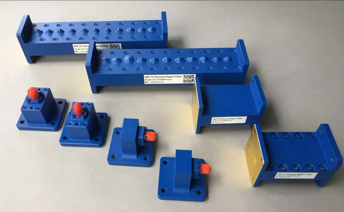
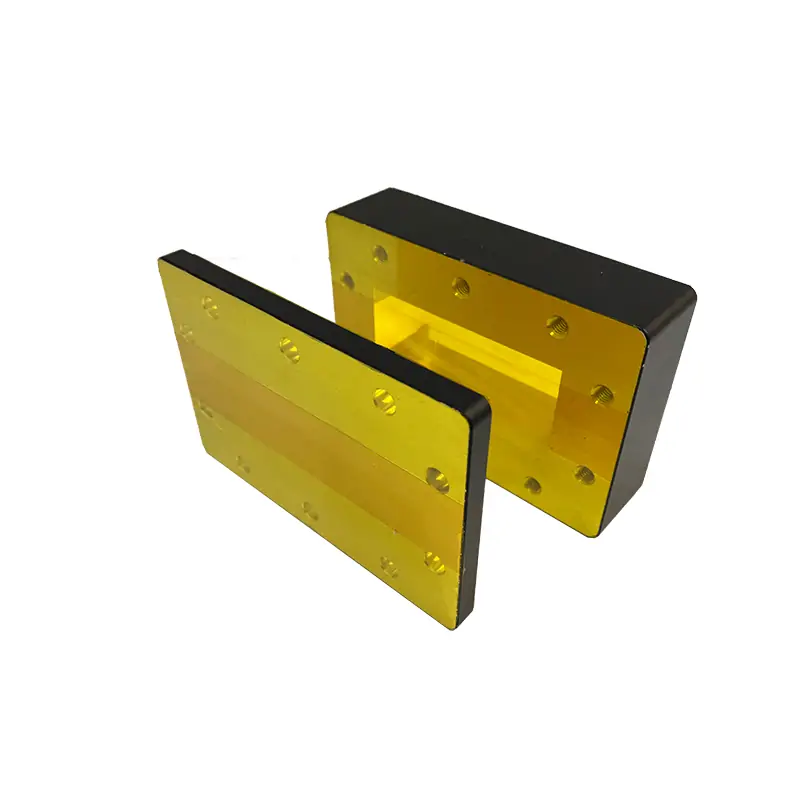
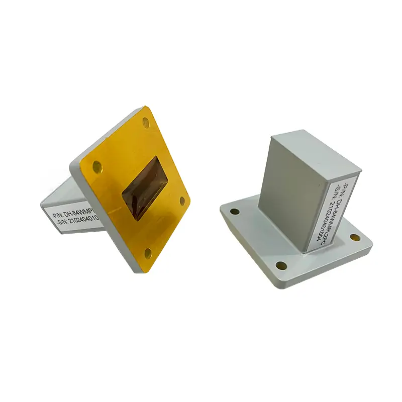
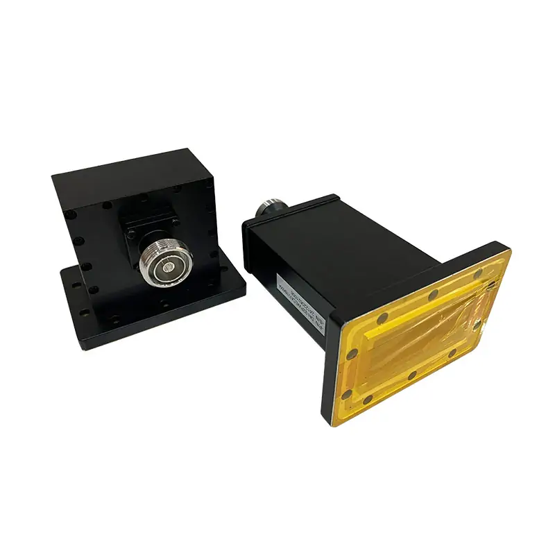
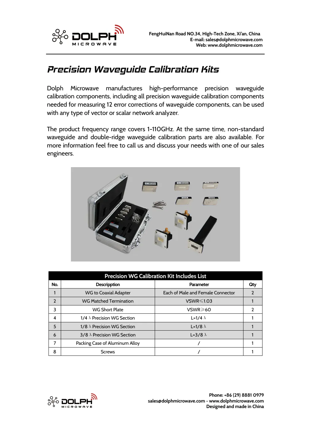
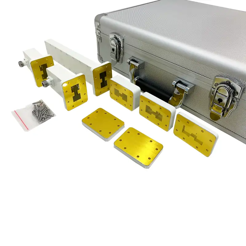
The calibration list includes waveguide-to-coaxial adapters, a matched termination, short plates and sections labelled 1/4λ, 1/8λ and 3/8λ, plus a case and screws. Confirm the definition frequency, physical lengths and electrical models for those labels. Catalogue and manual quantity lists remain separate pending the agreed bill of materials.
Verification kit
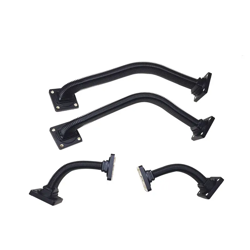
The verification set is listed separately and includes 20 dB and 50 dB attenuators, straight sections and a reflective load. Use independently characterized reference data and uncertainty to judge verification results; remeasuring calibration standards alone does not independently establish measurement accuracy. [1]
Frequency and method
The overview lists 1–110 GHz, while individual model rows collectively span 0.7–112.0 GHz. Select one compatible guide band and analyzer setup; these figures do not mean a single kit covers that entire interval. The legacy Anritsu 37369A example describes a procedure, not universal compatibility with every current analyzer.
Supplied data
Request the standard definitions in a format supported by the selected analyzer, along with reference-plane locations, characterization data and required uncertainty documentation. Dimensional tolerances and physical models affect calibrated S-parameter uncertainty; kit completeness alone does not establish it. [2]
Components and kit layouts
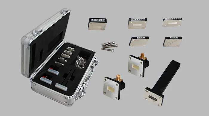
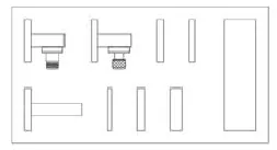
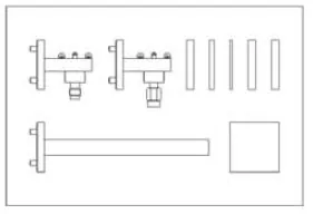
Specifications and configuration details
Precision WG calibration kit includes list — catalogue
| No. | Descripption | Parameter | Qty |
|---|---|---|---|
| 1 | WG to Coaxial Adapter | Each of Male and Female Connector | 2 |
| 2 | WG Matched Termination | VSWR≤1.03 | 1 |
| 3 | WG Short Plate | VSWR≥60 | 2 |
| 4 | 1/4λ Precision WG Section | L=1/4λ | 1 |
| 5 | 1/8λ Precision WG Section | L=1/8λ | 1 |
| 6 | 3/8λ Precision WG Section | L=3/8λ | 1 |
| 7 | Packing Case of Aluminum Alloy | / | 1 |
| 8 | Screws | / | 1 |
Precision WG calibration kit includes list — instruction manual
| No. | Descripption | Parameter | Qty |
|---|---|---|---|
| 1 | WG to Coaxial Adapter | Each of Male and Female Connector, VSWR≤1.25:1 | 2 |
| 2 | WG Matched Termination | VSWR≤1.03 | 1 |
| 3 | WG Short Plate | VSWR≥60 | 2 |
| 4 | 1/4λ Precision WG Section | L=1/4λ | 1 |
| 5 | 1/8λ Precision WG Section | L=1/8λ | 1 |
| 6 | 3/8λ Precision WG Section | L=3/8λ | 1 |
| 7 | Packing Case of Aluminum Alloy | / | 1 |
| 8 | Screws | / |
The manual adds an adapter VSWR value and leaves the screw quantity blank. Confirm the ordered kit contents.
Rectangle WG calibration kits
| Model No | WG Type EIA | Freq Range (GHz) | Connector | Flange | Material | Finish |
|---|---|---|---|---|---|---|
| DH-9VNAWKN | WR959 | 0.7-1.15 | N Female | FDP | Al | Chromate Conversion |
| DH-12VNAWKN | WR770 | 0.96-1.46 | N Female | FDP | Al | Chromate Conversion |
| DH-14VNAWKN | WR650 | 1.13-1.73 | N Female | FDP | Al | Chromate Conversion |
| DH-18VNAWKN | WR510 | 1.45-2.20 | N Female | FDP | Al | Chromate Conversion |
| DH-22VNAWKN | WR430 | 1.72-2.61 | N Female | FDP | Al | Chromate Conversion |
| DH-26VNAWKN | WR340 | 2.17-3.30 | N Female | FDP | Al | Chromate Conversion |
| DH-32VNAWKN | WR284 | 2.6-3.95 | N Female | FDP | Al | Chromate Conversion |
| DH-40VNAWKN | WR229 | 3.22-4.90 | N Female | FDP | Al | Chromate Conversion |
| DH-48VNAWKN | WR187 | 3.94-5.99 | N Female | FDP | Al | Chromate Conversion |
| DH-58VNAWKN | WR159 | 4.64-7.05 | N Female | FDP | Al | Chromate Conversion |
| DH-70VNAWKN | WR137 | 5.38-8.17 | N Female | FDP | Cu | Silver Plating |
| DH-84-VNAWKN | WR112 | 6.57-9.99 | N Female | FBP | Cu | Silver Plating |
| DH-100VNAWKN | WR90 | 8.20-12.4 | N Female | FBP | Cu | Silver Plating |
| DH-120VNAWKN | WR75 | 9.84-15.0 | N Female | FBP | Cu | Silver Plating |
| DH-140VNAWKS | WR62 | 11.9-18.0 | SMA Female | FBP | Cu | Silver Plating |
| DH-180VNAWKS | WR51 | 14.5-22.0 | SMA Female | FBP | Cu | Silver Plating |
| DH-220VNAWKK | WR42 | 17.6-26.7 | 2.92 Female | FBP | Cu | Silver Plating |
| DH-260VNAWKK | WR34 | 21.7-33.0 | 2.92 Female | FBP | Cu | Silver Plating |
| DH-320VNAWKK | WR28 | 26.5-40 | 2.92 Female | FBP | Cu | Silver Plating |
| DH-400VNAWKV | WR22 | 32.9-50.1 | 2.4 Female | FUGP | Cu | Silver Plating |
| DH-500VNAWK1.85 | WR19 | 39.2-59.6 | 1.85 Female | FUGP | Cu | Silver Plating |
| DH-620VNAWK1.85 | WR15 | 49.8-75.8 | 1.85 Female | FUGP | Cu | Silver Plating |
| DH-740WNAWK1.0 | WR12 | 60.5-91.9 | 1.0 Female | FUGP | Cu | Silver Plating |
| DH-900WNAWK1.0 | WR10 | 73.8-112.0 | 1.0 Female | FUGP | Cu | Silver Plating |
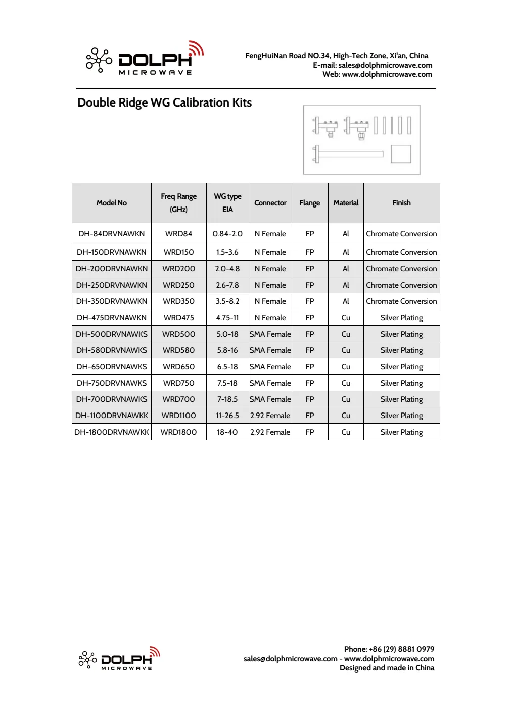
Double Ridge WG calibration kits
| Model No | WG type EIA | Freq Range (GHz) | Connector | Flange | Material | Finish |
|---|---|---|---|---|---|---|
| DH-84DRVNAWKN | WRD84 | 0.84-2.0 | N Female | FP | Al | Chromate Conversion |
| DH-150DRVNAWKN | WRD150 | 1.5-3.6 | N Female | FP | Al | Chromate Conversion |
| DH-200DRVNAWKN | WRD200 | 2.0-4.8 | N Female | FP | Al | Chromate Conversion |
| DH-250DRVNAWKN | WRD250 | 2.6-7.8 | N Female | FP | Al | Chromate Conversion |
| DH-350DRVNAWKN | WRD350 | 3.5-8.2 | N Female | FP | Al | Chromate Conversion |
| DH-475DRVNAWKN | WRD475 | 4.75-11 | N Female | FP | Cu | Silver Plating |
| DH-500DRVNAWKS | WRD500 | 5.0-18 | SMA Female | FP | Cu | Silver Plating |
| DH-580DRVNAWKS | WRD580 | 5.8-16 | SMA Female | FP | Cu | Silver Plating |
| DH-650DRVNAWKS | WRD650 | 6.5-18 | SMA Female | FP | Cu | Silver Plating |
| DH-750DRVNAWKS | WRD750 | 7.5-18 | SMA Female | FP | Cu | Silver Plating |
| DH-700DRVNAWKS | WRD700 | 7-18.5 | SMA Female | FP | Cu | Silver Plating |
| DH-1100DRVNAWKK | WRD1100 | 11-26.5 | 2.92 Female | FP | Cu | Silver Plating |
| DH-1800DRVNAWKK | WRD1800 | 18-40 | 2.92 Female | FP | Cu | Silver Plating |
The PDF prints the second and third column headings in the opposite order to their cell contents. The actual waveguide identifiers and frequencies are retained here under their corresponding labels; the original page is included below.
Drawings and original documents
PRECISION WAVEGUIDE CALIBRATION KITS
Download PDFView original pages (3)
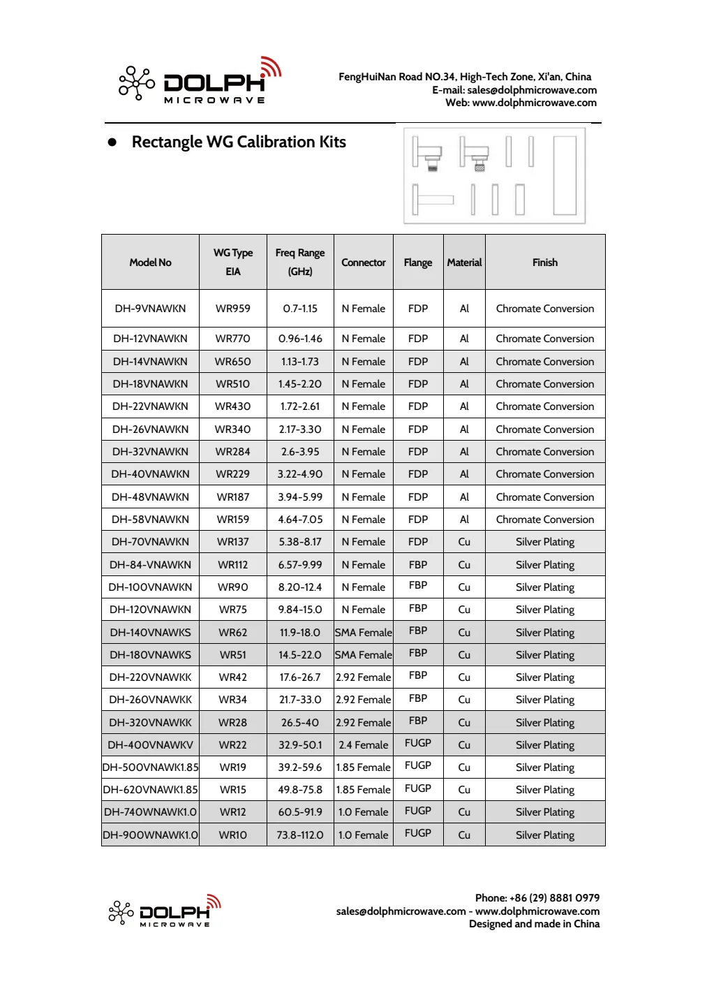
WAVEGUIDE CALIBRATION KIT INSTRUCTION MANUAL
Download PDFTwelve-page source manual. It uses an Anritsu 37369A example; confirm the procedure and calibration definitions for your analyzer.
Related products
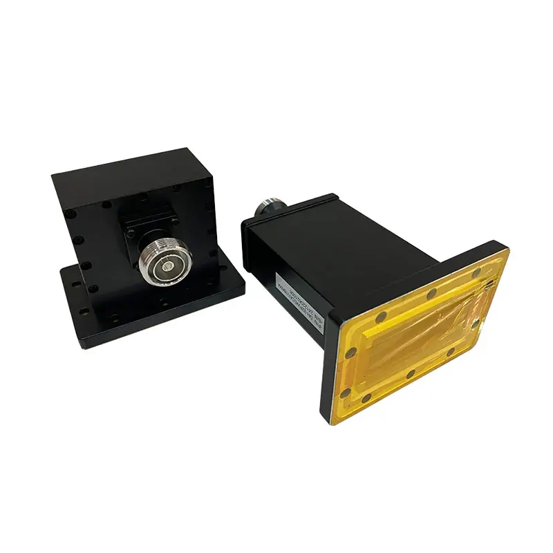
For a different kit configuration, see Precision Waveguide Calibration Kits. Check the coaxial interface against the Waveguide to Coaxial Adapters.

Include these details in your inquiry
- Waveguide size and measurement frequency range
- Exact flange and connector interfaces
- Analyzer manufacturer and model
- Intended calibration method
- Required calibration definitions and verification scope
- Component quantities and documentation requirements