
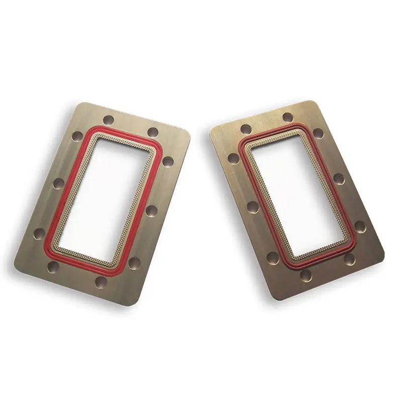
Waveguide Flange Shim
Waveguide flange shims are precision components used to ensure proper alignment and sealing between waveguide sections in microwave systems. These thin metal spacers adjust the mating surfaces for optimal connection, enhancing system performance by preventing air gaps and ensuring efficient signal transmission across various applications.
Precision aluminum and copper spacers for controlled waveguide flange spacing, alignment and interface adjustment across 0.32–112 GHz. Published configurations cover 1–50 mm thicknesses with model-dependent cover, grooved and other flange interfaces. Custom thickness, material, finish and sealing requirements can be reviewed against the mating-flange drawing.
A configurable interface component for standard rectangular waveguide systems
A waveguide flange shim is installed between compatible mating interfaces when a defined mechanical spacing or flange adjustment is required. The selected part must match the waveguide aperture, flange family, bolt or alignment arrangement, material and finished thickness specified by the assembly drawing.
Define the sealing function separately
A shim can support the required spacing and mating geometry, but the shim alone does not establish a pressure rating, moisture seal or RF seal. A sealed assembly requires a compatible flange pair, the specified gasket or O-ring, controlled compression and an agreed leakage or pressure acceptance method.
Confirm the complete interface—not only the WR size
The WR designation identifies the nominal waveguide size, but it does not fully define the flange face, groove, hole pattern, alignment arrangement or required sealing system.
Operating band
Provide the complete minimum-to-maximum operating frequency, not only the center frequency.
Waveguide size
Confirm the applicable WR and IEC/R designation shown in the project documentation.
Flange designation
State the complete cover, grooved, choke, CPR, PBR, UBR, UDR, UG or project-specific code.
Thickness and material
Define finished thickness, tolerance and the required aluminum or copper configuration.
Drawing and acceptance
Approve the mating-interface drawing and agree any dimensional, RF, pressure or documentation requirements.
Cover, grooved and choke interfaces require different mating details
Dolph publishes IEC and EIA flange designation references across the standard rectangular waveguide range. Use the exact flange code and mating drawing when selecting a shim; similarly named flanges are not automatically interchangeable.
Review EIA and IEC flange referencesCover / flat interface
Confirm the aperture, outer dimensions, hole pattern, alignment features and the compatible mating face.
Grooved interface
Confirm groove dimensions and the specified gasket or O-ring. A groove alone does not define pressure capability.
Choke or special interface
Use the controlled interface drawing to verify choke geometry, orientation and the approved mating configuration.
Interface details can be reviewed alongside the wider waveguide assembly
Dolph Microwave states that it was founded in 2001 and manufactures microwave components and antenna feed systems. Published manufacturing capabilities include CNC machining, turning, waveguide forming and bending, soldering and brazing of copper, copper alloys and aluminum, plating, passivation and assembly.
For models operating above 100 GHz, confirm the applicable measurement method, test range and deliverable documentation before ordering. The validity date printed on the currently published ISO certificate is August 7, 2026; verify the current certificate status when certification evidence is required.
Waveguide flange shim model table
The table retains the model, frequency range, waveguide size, published VSWR, flange designation, thickness, material, finish and document fields shown in the current product data.
View all 29 published model rows
| Model | Frequency (GHz) |
WG Size | VSWR | Flange Type / Designation | Thickness (mm) |
Material | Finish | Files | |
|---|---|---|---|---|---|---|---|---|---|
| Cover | Grooved | ||||||||
| DH-3WG… | 0.32–0.49 | WR2300 | 1.05:1 | UDR3 | PDR3 | 1–50 | Al | Chromate | PDFSTEP |
| DH-4WG… | 0.35–0.53 | WR2100 | 1.05:1 | UDR4 | PDR4 | 1–50 | Al | Chromate | PDFSTEP |
| DH-5WG… | 0.41–0.62 | WR1800 | 1.05:1 | UDR5 | PDR5 | 1–50 | Al | Chromate | PDFSTEP |
| DH-6WG… | 0.49–0.75 | WR1500 | 1.05:1 | UDR6 | PDR6 | 1–50 | Al | Chromate | PDFSTEP |
| DH-8WG… | 0.64–0.98 | WR1150 | 1.05:1 | UDR8 | PDR8 | 1–50 | Al | Chromate | PDFSTEP |
| DH-9WG… | 0.76–1.15 | WR975 | 1.05:1 | UDR9 | PDR9 | 1–50 | Al | Chromate | PDFSTEP |
| DH-12WG… | 0.96–1.46 | WR770 | 1.05:1 | UDR12 | PDR12 | 1–50 | Al | Chromate | PDFSTEP |
| DH-14WG… | 1.13–1.73 | WR650 | 1.05:1 | UDR14 | PDR14 | 1–50 | Al | Chromate | PDFSTEP |
| DH-18WG… | 1.45–2.2 | WR510 | 1.05:1 | UDR18 | PDR18 | 1–50 | Al | Chromate | PDFSTEP |
| DH-22WG… | 1.72–2.61 | WR430 | 1.05:1 | UDR22 | PDR22 | 1–50 | Al/Cu | Chromate | PDFSTEP |
| DH-26WG… | 2.17–3.3 | WR340 | 1.05:1 | UDR26 | PDR26 | 1–50 | Al/Cu | Chromate | PDFSTEP |
| DH-32WG… | 2.6–3.95 | WR284 | 1.05:1 | UDR32 | PDR32 | 1–50 | Al/Cu | Chromate | PDFSTEP |
| DH-40WG… | 3.22–4.9 | WR229 | 1.05:1 | UDR40 | PDR40 | 1–50 | Al/Cu | Chromate | PDFSTEP |
| DH-48WG… | 3.94–5.99 | WR187 | 1.05:1 | UDR48 | PDR348 | 1–50 | Al/Cu | Chromate | PDFSTEP |
| DH-58WG… | 4.64–7.05 | WR159 | 1.05:1 | UDR58 | PDR58 | 1–50 | Al/Cu | Chromate | PDFSTEP |
| DH-70WG… | 5.38–8.17 | WR137 | 1.05:1 | UDR70 | PDR70 | 1–50 | Al/Cu | Chromate | PDFSTEP |
| DH-84WG… | 6.57–9.99 | WR112 | 1.05:1 | UDR84/UBR84 | PDR84/PBR84 | 1–50 | Al/Cu | Chromate | PDFSTEP |
| DH-100WG… | 8.2–12.5 | WR90 | 1.05:1 | UDR100/UBR100 | PDR100/PBR100 | 1–50 | Al/Cu | Chromate | PDFSTEP |
| DH-120WG… | 9.84–15 | WR75 | 1.05:1 | UBR120 | PBR120 | 1–50 | Al/Cu | Chromate | PDFSTEP |
| DH-140WG… | 11.9–18 | WR62 | 1.05:1 | UBR140 | PBR140 | 1–50 | Al/Cu | Chromate | PDFSTEP |
| DH-180WG… | 14.5–22 | WR51 | 1.05:1 | UBR180 | PBR180 | 1–50 | Al/Cu | Chromate | PDFSTEP |
| DH-220WG… | 17.6–26.7 | WR42 | 1.05:1 | UBR220 | PBR220 | 1–50 | Al/Cu | Chromate | PDFSTEP |
| DH-260WG… | 21.7–33 | WR34 | 1.05:1 | UBR260 | PBR260 | 1–50 | Al/Cu | Chromate | PDFSTEP |
| DH-320WG… | 26.3–40 | WR28 | 1.05:1 | UBR320 | PBR320 | 1–50 | Al/Cu | Chromate | PDFSTEP |
| DH-400WG… | 32.9–50.1 | WR22 | 1.05:1 | FUGP400/UG-383U/M | 1–50 | Cu | Chromate | PDFSTEP | |
| DH-500WG… | 39.2–59.6 | WR19 | 1.05:1 | FUGP500/UG-383U/M | 1–50 | Cu | Chromate | PDFSTEP | |
| DH-620WG… | 49.8–75.8 | WR15 | 1.05:1 | FUGP620/UG-385U/M | 1–50 | Cu | Chromate | PDFSTEP | |
| DH-740WG… | 60.5–91.9 | WR12 | 1.05:1 | FUGP740/UG-387U/M | 1–50 | Cu | Chromate | PDFSTEP | |
| DH-900WG… | 73.8–112 | WR10 | 1.05:1 | FUGP900/UG-387U/M | 1–50 | Cu | Chromate | PDFSTEP | |
Model and flange codes above reproduce the current product table, including the published “PDR348” entry for DH-48WG. Confirm the final model code, flange designation and approved drawing with Dolph Microwave before production or replacement procurement. STEP availability should also be confirmed for the selected model.
Published part-number guide
The current product page gives the following ordering example. Use it as a reference and confirm the final code in the quotation or approved drawing.
Published surface treatment
The product note states that Dolph-MW models include Surtec/corrosion-protection treatment and flat-black paint. Flanges are described as unplated, polished and Surtec-treated.
Alternative finishes
Other finishes and paint colors are stated as available on request. Define the required finish in the RFQ rather than assuming the catalog finish will apply to a custom build.
Drawing-controlled supply
For replacement, integration or non-standard applications, use the approved drawing to control thickness, aperture, holes, groove geometry, material, finish and inspection requirements.
Information to include with your enquiry
A complete technical package helps the sales and engineering teams assess compatibility without relying on assumptions.
Coordinate the shim with the adjoining interface components
These related product families can be reviewed when the requirement involves a complete waveguide joint, replacement section, sealing arrangement or flange standard.
 Related product
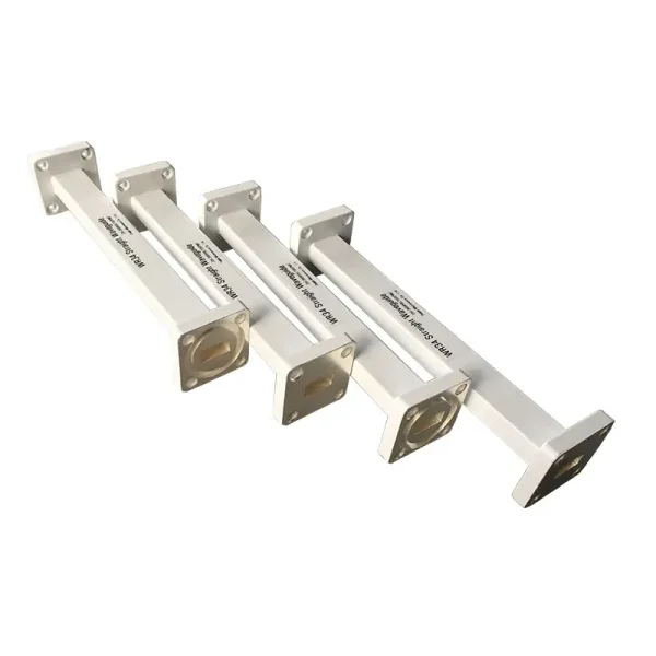
Straight Waveguide Sections
Review complete straight sections when the required spacing cannot be addressed by a flange shim alone.
 Sealing component
Waveguide Gasket and O-Ring
Select conductive or non-conductive sealing materials according to the specified pressure and RF function.
 Interface reference
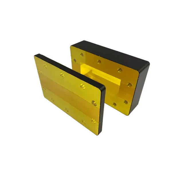
Waveguide Flange Standard EIA & IEC
Compare published flange families and designation codes before confirming the mating interface.
Raw waveguideWaveguide Tube
Review raw rectangular waveguide tubing for cut-length supply or a drawing-controlled fabricated assembly.
Flange selection and assembly references
Review these supporting guides when identifying an existing flange, selecting a gasket or preparing the installation procedure.
Technical documents
Use the published product sheet for preliminary selection and the flange reference for designation comparison. The approved quotation and drawing should control the final supply.
One year from the date of delivery
Dolph Microwave states that its products are warranted against defective material and workmanship for one year from delivery. Defective parts and repair work required by normal use are covered within that period, subject to the published warranty wording and applicable commercial terms.
Confirm your required interface
Send the operating band, WR size, mating flange drawing, thickness, material, finish, sealing function, quantity and required documentation for technical review.
Contact Dolph Microwave






