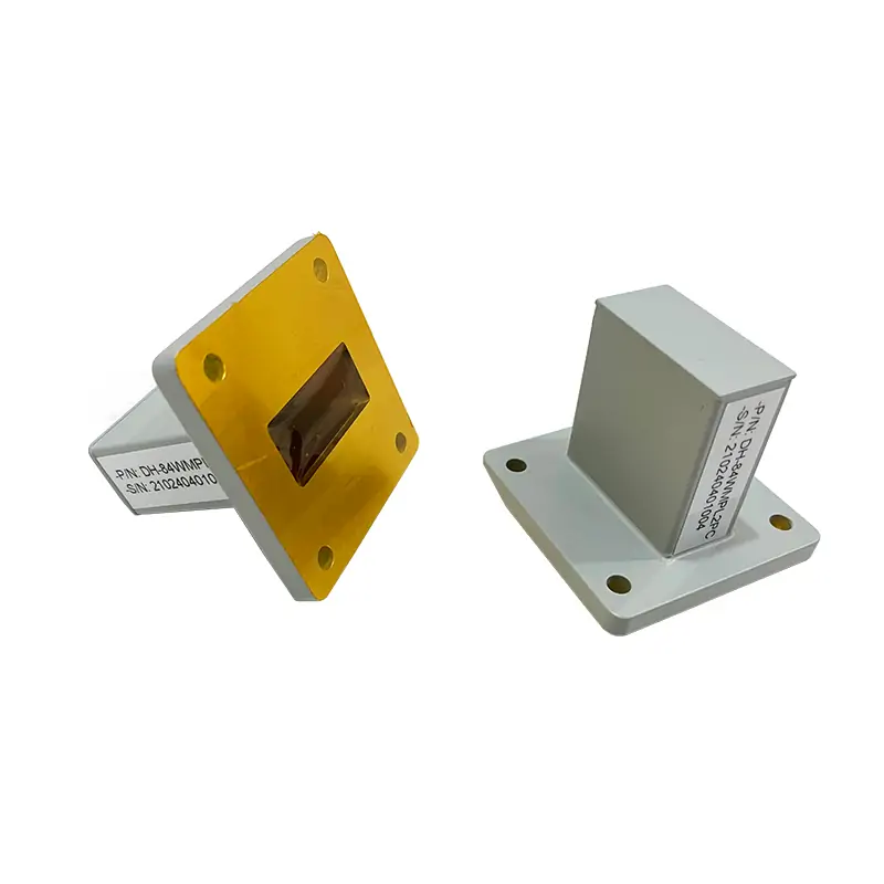
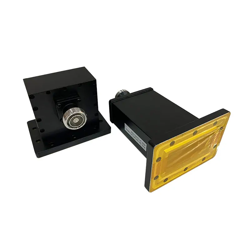
Waveguide Pressure Inlets Section
Waveguide pressure inlet sections provide a gas connection to a pressurized waveguide line, with valve and gauge options. Match the WR size, flange arrangement, exact inlet thread and configuration-specific pressure requirement.
PRESSURIZED WAVEGUIDE HARDWARE
Waveguide Pressure Inlet Sections
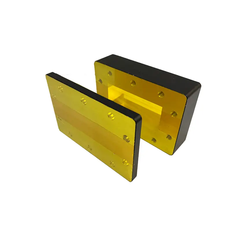
Dolph Microwave pressure inlet sections introduce air or other gases into a waveguide line while supporting controlled internal pressure. Configurations are available with or without a pressure gauge, with cover, grooved or choke flange options, and with standard or customized mechanical configurations for the selected waveguide system.
CONFIGURATION SUPPORT
Match the inlet section to your waveguide line
Send the operating band and waveguide size together with the required pressure, inlet connection, valve, length, flange style, material and gauge requirement. Dolph Microwave can then match a published configuration or discuss a customized mechanical configuration for the application.
Waveguide & band
Start with the WR size and operating frequency range so the mechanical section matches the line.
Pressure & monitoring
Select the required pressure range and whether an integrated pressure gauge is needed.
Inlet, valve & length
The WPI brochure lists a 1/8-27 NPT inlet and thicknesses of 50 or 19 mm by model. The separate WPISV valve configuration below lists NPTF and different lengths.
Flange & material
Choose the applicable cover, grooved or choke flange configuration and confirm the material/finish for the selected model.
OFFICIAL PRODUCT BROCHURE
WPI model specifications — from the product PDF
The WPI brochure lists separate models from WR650 through WR10. Its thickness field is 50 mm for WR650/WR510 and 19 mm for the remaining rows. Do not substitute these thicknesses for the 19/108/152 mm WPISV length options without a matching drawing. The WR90 upper band edge is 12.40 GHz in this table and 12.5 GHz in the WPISV table; confirm the required endpoint in the RF acceptance specification.
| Model | WR Type | Frequency (GHz) | VSWR Max. | Thickness (mm) | Pressure (PSIG) |
|---|---|---|---|---|---|
| DH-14WPI… | WR650 | 1.13-1.73 | 1.05 | 50 | 15-45 |
| DH-18WPI… | WR510 | 1.45-2.20 | 1.05 | 50 | 15-45 |
| DH-22WPI… | WR430 | 1.72-2.61 | 1.05 | 19 | 15-45 |
| DH-26WPI… | WR340 | 2.17-3.30 | 1.05 | 19 | 15-45 |
| DH-32WPI… | WR284 | 2.60-3.95 | 1.05 | 19 | 15-45 |
| DH-40WPI… | WR229 | 3.22-4.9 | 1.05 | 19 | 15-45 |
| DH-48WPI… | WR187 | 3.94-5.99 | 1.05 | 19 | 15-45 |
| DH-58WPI… | WR159 | 4.64-7.05 | 1.05 | 19 | 15-45 |
| DH-70WPI… | WR137 | 5.38-8.17 | 1.05 | 19 | 15-45 |
| DH-84WPI… | WR112 | 6.57-9.99 | 1.05 | 19 | 15-45 |
| DH-100WPI… | WR90 | 8.20-12.40 | 1.05 | 19 | 15-45 |
| DH-120WPI… | WR75 | 9.84-15.0 | 1.05 | 19 | 15-45 |
| DH-140WPI… | WR62 | 11.9-18.0 | 1.05 | 19 | 15-45 |
| DH-180WPI… | WR51 | 14.5-22.0 | 1.05 | 19 | 15-45 |
| DH-220WPI… | WR42 | 17.6-26.7 | 1.05 | 19 | 15-45 |
| DH-260WPI… | WR34 | 21.7-33.0 | 1.05 | 19 | 15-45 |
| DH-320WPI… | WR28 | 26.3-40.0 | 1.05 | 19 | 15-45 |
| DH-400WPI… | WR22 | 33.0-50.0 | 1.05 | 19 | 15-20 |
| DH-500WPI… | WR19 | 40.0-60.0 | 1.05 | 19 | 15-20 |
| DH-620WPI… | WR15 | 55.0-65.0 | 1.05 | 19 | 15-20 |
| DH-740WPI… | WR12 | 60.5-91.9 | 1.05 | 19 | 15-20 |
| DH-900WPI… | WR10 | 73.8-112.0 | 1.05 | 19 | 15-20 |
Inlet thread, base metal and finish
| Selection item | What to specify |
|---|---|
| Inlet thread | The WPI brochure lists 1/8-27 NPT. The additional WPISV valve table lists 1/8-27 NPTF. Keep the thread designation with its configuration and specify the mating thread and sealing procedure. Dryseal threads have different crest/root controls from standard pipe threads; matching nominal size and pitch alone does not define the same pressure-tight joint.[1] |
| Material and finish | The PDF features list aluminum and copper, its finish table lists brass, and its ordering example identifies A as aluminum. Specify the base alloy and treated surfaces on the order drawing. MIL-C-5541/MIL-DTL-5541 concerns conversion coatings on aluminum and aluminum alloys; the PDF’s brass/Iridite combination is not a consistent material-and-finish specification.[2] |
SCHRADER-VALVE CONFIGURATIONS
WPISV Schrader-valve configuration — additional option
This separate WPISV table retains the website’s Schrader-valve configuration data. It is not the WPI table in the linked PDF. Its 45 PSIG, NPTF thread and length options apply only to the stated valve configuration; do not substitute them for the WPI brochure values above.
| MODEL | FREQ. RANGE (GHz) | WG SIZE | VSWR | PRESSURE (PSIG) | INLET SIZE (CUSTOMIZABLE) | GAS VALVES | LENGTH (mm) | COVER | GROOVED | MATERIAL | DATASHEET |
|---|---|---|---|---|---|---|---|---|---|---|---|
| DH-14WPISV… | 1.13-1.73 | WR650 | 1.05:1 | 45 | 1/8-27 NPTF | Schrader Valves | 19, 108,152 | UDR14 | PDR14 | Al | DWG / STEP on request |
| DH-18WPISV… | 1.45-2.2 | WR510 | 1.05:1 | 45 | 1/8-27 NPTF | Schrader Valves | 19, 108,152 | UDR18 | PDR18 | Al | DWG / STEP on request |
| DH-22WPISV… | 1.72-2.61 | WR430 | 1.05:1 | 45 | 1/8-27 NPTF | Schrader Valves | 19, 108,152 | UDR22 | PDR22 | Al | DWG / STEP on request |
| DH-26WPISV… | 2.17-3.3 | WR340 | 1.05:1 | 45 | 1/8-27 NPTF | Schrader Valves | 19, 108,152 | UDR26 | PDR26 | Al | DWG / STEP on request |
| DH-32WPISV… | 2.6-3.95 | WR284 | 1.05:1 | 45 | 1/8-27 NPTF | Schrader Valves | 19, 108,152 | UDR32 | PDR32 | Al | DWG / STEP on request |
| DH-40WPISV… | 3.22-4.9 | WR229 | 1.05:1 | 45 | 1/8-27 NPTF | Schrader Valves | 19, 108,152 | UDR40 | PDR40 | Al | DWG / STEP on request |
| DH-48WPISV… | 3.94-5.99 | WR187 | 1.05:1 | 45 | 1/8-27 NPTF | Schrader Valves | 19, 108,152 | UDR48 | PDR48 | Al | DWG / STEP on request |
| DH-58WPISV… | 4.64-7.05 | WR159 | 1.05:1 | 45 | 1/8-27 NPTF | Schrader Valves | 19, 108,152 | UDR58 | PDR58 | Al | DWG / STEP on request |
| DH-70WPISV… | 5.38-8.17 | WR137 | 1.05:1 | 45 | 1/8-27 NPTF | Schrader Valves | 19, 108,152 | UDR70 | PDR70 | Al | DWG / STEP on request |
| DH-84WPISV… | 6.57-9.99 | WR112 | 1.05:1 | 45 | 1/8-27 NPTF | Schrader Valves | 19, 108,152 | UDR84/UBR84 | PDR84/PBR84 | Al | DWG / STEP on request |
| DH-100WPISV… | 8.2-12.5 | WR90 | 1.05:1 | 45 | 1/8-27 NPTF | Schrader Valves | 19, 108,152 | UDR100/UBR100 | PDR100/PBR100 | Al | DWG / STEP on request |
| DH-120WPISV… | 9.84-15 | WR75 | 1.05:1 | 45 | 1/8-27 NPTF | Schrader Valves | 19, 108,152 | UBR120 | PBR120 | Al | DWG / STEP on request |
| DH-140WPISV… | 11.9-18 | WR62 | 1.05:1 | 45 | 1/8-27 NPTF | Schrader Valves | 19, 108,152 | UBR140 | PBR140 | Al | DWG / STEP on request |
| DH-180WPISV… | 14.5-22 | WR51 | 1.05:1 | 45 | 1/8-27 NPTF | Schrader Valves | 19, 108,152 | UBR180 | PBR180 | Al | DWG / STEP on request |
| DH-220WPISV… | 17.6-26.7 | WR42 | 1.05:1 | 45 | 1/8-27 NPTF | Schrader Valves | 19, 108,152 | UBR220 | PBR220 | Al/Cu | DWG / STEP on request |
| DH-260WPISV… | 21.7-33 | WR34 | 1.05:1 | 45 | 1/8-27 NPTF | Schrader Valves | 19, 108,152 | UBR260 | PBR260 | Al/Cu | DWG / STEP on request |
| DH-320WPISV… | 26.3-40 | WR28 | 1.05:1 | 45 | 1/8-27 NPTF | Schrader Valves | 19, 108,152 | UBR320 | PBR320 | Al/Cu | DWG / STEP on request |
Source: Dolph product brochure, printed pages 081–082. All 22 WPI rows specify maximum VSWR 1.05. WR650 and WR510 have a listed thickness of 50 mm; the remaining rows list 19 mm. Pressure is listed as 15–45 PSIG for WR650–WR28 and 15–20 PSIG for WR22–WR10. The PDF does not identify a separate proof-test pressure or leak-test procedure.
PART NUMBER GUIDE
WPISV valve option code
Product-page example: DH-100WPISV152PMA
100Waveguide Size — WR90WPIWaveguide Type — Waveguide Pressure InletsSV152Schrader-valve section, length 152 mm. Specify the gauge option separately and request the complete order code.108Length — 108 mm, Pressurizing Section with Schrader Valves19Length — 19 mm, Flange Spacer InletsPFlange Type — Rectangular FlatMFlange Type — Rectangular GroovedA/CMaterial — Aluminium, CuBROCHURE ORDERING INFORMATION
WPI ordering example from the PDF
Brochure example: DH – 120 WPI 19 P M A
DHDolph Microwave120WR75WPIPressure InletsWPISGInlets Section with Pressure Gauge19Thickness 19 mmPFlange CoverMFlange GroovedAMaterial AlFINISH & MECHANICAL OPTIONS
Surface treatment and configuration details
WHY IT MATTERS IN THE LINE
Define pressure access and RF acceptance together
The inlet provides a gas connection; it does not replace a regulator, relief device or leak test. Specify the gas, maximum differential pressure, permitted leak rate, gauge range and operating temperature. Check assembled VSWR across the required band, including the inlet and mating flanges.
APPLICATIONS
Installation checks by application
Radar systems
For radar feed lines, specify the pressure medium, RF power, flange arrangement and installation orientation.
Telecommunications
For long communication runs, identify the gas supply, regulator, low-pressure monitoring and accessible service position.
Satellite communications
For antenna feeds, check clearance around the feed support and access to the valve and gauge after installation.
Scientific research
For laboratory setups, define the pressure sequence, temperature, leak-rate limit and RF measurements in the test plan.
Aerospace
For aerospace assemblies, specify the applicable vibration, temperature, material and documentation requirements; qualification is configuration-specific.
DOCUMENTATION & SUPPORT
Order against the selected model and drawing
For quotation, include the required WR size, frequency range, operating pressure, inlet size, gauge requirement, flange type, length and material. Where published data differs by source or configuration, use the final selected drawing and confirmed order specification.
REQUEST A CONFIGURATION
Send your waveguide and pressure requirements
Include the WR size, frequency, pressure, inlet connection, valve, length, flange, material and gauge requirement so the suitable pressure inlet section can be identified.