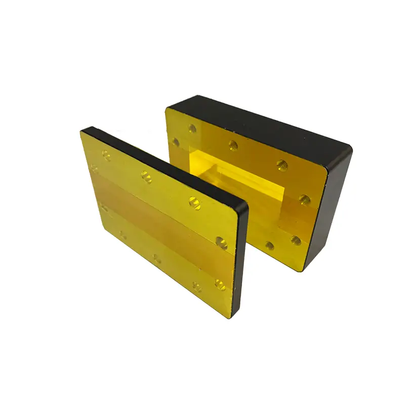
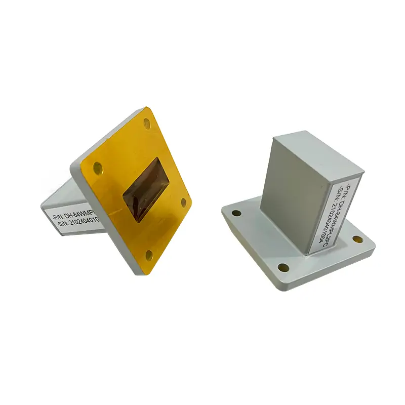
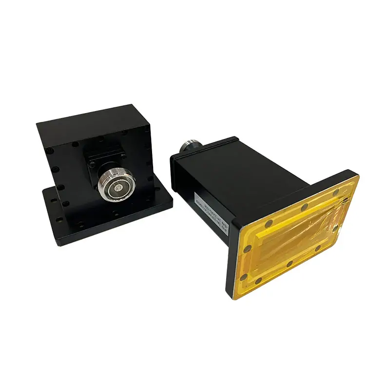
Double-Ridged Waveguide / Fixed Attenuation
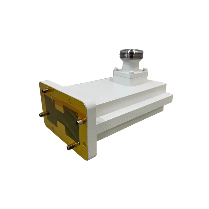
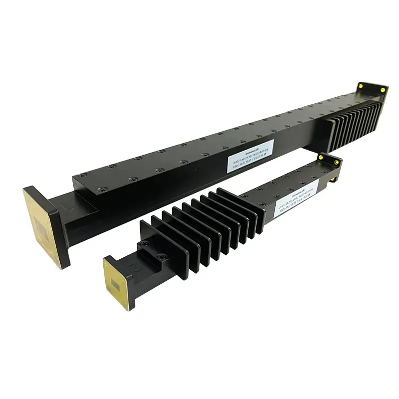
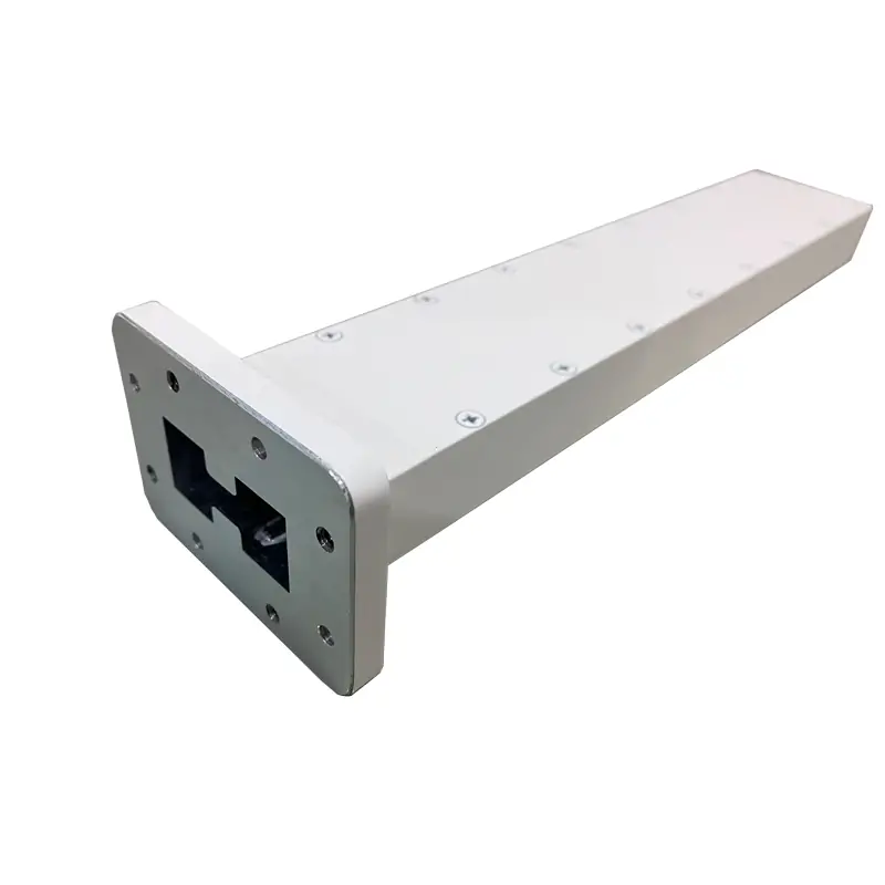
High Power Double-Ridged Waveguide Fixed Attenuator
For double-ridged waveguide systems that need a fixed drop in RF level while the signal continues through the line. The published family covers 0.84–40 GHz, 10–60 dB attenuation and model-dependent CW ratings from 100 to 4,000 W. Pick the exact WRD size and flange pair from the table before ordering.

Start here
Choose the row that matches your real system
The whole family spans 0.84–40 GHz, but one attenuator does not cover that entire range. Each WRD size has its own band and power range.
If you already know the waveguide size, go straight to the model table. If you only know the frequency, use the band to narrow the choice, then check the flange and power.
- Full operating band: send the lowest and highest frequency, not only the center frequency.
- Attenuation: state the fixed value you need in dB.
- Power: state CW power; for pulsed systems also send peak power, pulse width and duty cycle.
- Interface: match the WRD size and the exact cover/grooved flange code.

Fit check
Use this product when the RF path must continue at a lower level
A fixed attenuator sits in the waveguide path and reduces the signal by a set amount. It is a different job from a termination, which ends the RF path, or a waveguide-to-coax adapter, which changes the interface.
If the surrounding system is still being defined, browse the double-ridged waveguide component family before locking the attenuator interface.
Use one published model row. Do not combine the band from one row with the flange or power figure from another.
The listed family range is 10–60 dB. Put the required value directly in the RFQ and part-number review.
The highest family figure is not the rating of every model. Published limits fall as the WRD size changes.
Cover and grooved flange codes are listed separately. Check the mating component or drawing before release.
Published model data
High Power Fixed Attenuator specifications
All published model rows are kept below so purchasing and engineering can work from the same data. On mobile, swipe the table horizontally.
| MODEL | FREQ. RANGE (GHz) | WG SIZE | VSWR Max. | ATT. (dB) | FREQ. RESPONSE (dB) | AVG POWER CW (W) | FLANGE — COVER | FLANGE — GROOVED | MATERIAL | FINISH | DATASHEET | 3D MODEL |
|---|---|---|---|---|---|---|---|---|---|---|---|---|
| DH-840DRWHPFA… | 0.84-2.0 | WRD840 | 1.15:1 | 10-60 | ±2.0 | 100-4000 | FPWRD840U24 | FMWRD840U24 | Al/Cu | Chromate/Painted | STEP | |
| DH-150DRWHPFA… | 1.5-3.6 | WRD150 | 1.15:1 | 10-60 | ±2.0 | 100-4000 | FPWRD150D24 | FMWRD150D24 | Al/Cu | Chromate/Painted | STEP | |
| DH-200DRWHPFA… | 2.0-4.8 | WRD200 | 1.15:1 | 10-60 | ±2.0 | 100-4000 | FPWRD200D24 | FMWRD200D24 | Al/Cu | Chromate/Painted | STEP | |
| DH-250DRWHPFA… | 2.6-7.8 | WRD250 | 1.15:1 | 10-60 | ±2.0 | 100-4000 | FPWRD250D30 | FMWRD250D30 | Al/Cu | Chromate/Painted | STEP | |
| DH-350DRWHPFA… | 3.5-8.2 | WRD350 | 1.15:1 | 10-60 | ±2.0 | 100-2000 | FPWRD350D24 | FMWRD350D24 | Al/Cu | Chromate/Painted | STEP | |
| DH-475DRWHPFA… | 4.75-11.0 | WRD475 | 1.15:1 | 10-60 | ±2.0 | 100-2000 | FPWRD475D24 | FMWRD475D24 | Al/Cu | Chromate/Painted | STEP | |
| DH-500DRWHPFA… | 5.0-18.0 | WRD500 | 1.15:1 | 10-60 | ±2.0 | 100-2000 | FPWRD500D36 | FMWRD500D36 | Al/Cu | Chromate/Painted | STEP | |
| DH-580DRWHPFA… | 5.8-16.0 | WRD580 | 1.15:1 | 10-60 | ±2.0 | 100-1500 | FPWRD580D28 | FMWRD580D28 | Al/Cu | Chromate/Painted | STEP | |
| DH-650DRWHPFA… | 6.5-18.0 | WRD650 | 1.15:1 | 10-60 | ±2.0 | 100-1500 | FPWRD650D28 | FMWRD650D28 | Al/Cu | Chromate/Painted | STEP | |
| DH-700DRWHPFA… | 7.0-18.5 | WRD700 | 1.15:1 | 10-60 | ±2.0 | 100-1500 | FPWRD700D26 | FMWRD700D26 | Al/Cu | Chromate/Painted | STEP | |
| DH-750DRWHPFA… | 7.5-18.0 | WRD750 | 1.15:1 | 10-60 | ±2.0 | 100-1000 | FPWRD750D24 | FMWRD750D24 | Al/Cu | Chromate/Painted | STEP | |
| DH-110DRWHPFA… | 11.0-26.5 | WRD110 | 1.15:1 | 10-60 | ±2.5 | 100-1000 | FPWRD110C24 | FMWRD110C24 | Al/Cu | Chromate/Painted | STEP | |
| DH-180DRWHPFA… | 18.0-40.0 | WRD180 | 1.15:1 | 10-60 | ±2.5 | 100-1000 | FPWRD180C24 | FMWRD180C24 | Al/Cu | Chromate/Painted | STEP |
Power-unit check: the current page’s table heading shows “KW”, while the same page says the family reaches 4 kW and the ordering example defines “1000” as 1000 W CW. The table above therefore displays the published numeric values as watts. Confirm the final power unit and rating on the approved quotation/drawing before production release.
What changes from model to model
The family maximum is not your model rating
This is the main point to check before sending a purchase request. The lower-frequency WRD840 through WRD250 rows list up to 4,000 W CW, while the higher-frequency rows list lower maximum values.
Frequency response
WRD840 through WRD750 rows list ±2.0 dB. WRD110 and WRD180 list ±2.5 dB.
VSWR
Every listed model row shows 1.15:1 maximum.
Material and finish
Every listed row shows Al/Cu material and Chromate/Painted finish.
Flanges
Cover and grooved flange codes change with WRD size. Treat those codes as part of the model selection, not an accessory choice after the fact.
Ordering reference
Read the part number before you send the RFQ
The current product page gives this example. It packs the waveguide size, attenuator type, attenuation, flange pair, material and power into one code.
All Dolph-MW models include an surtec/corrosion protection treatment and are painted flat black. Flanges are unplated, polished and surtec. Other finishes and paint colors are available upon request.
Typical system use
Where a fixed high-power attenuator fits
The exact application matters less than the RF conditions. In each case below, the attenuator still has to be checked against the actual band, WRD interface and power.
Radar RF paths
Fixed signal reduction in a compatible double-ridged waveguide transmission path.
Satellite communications
Power-level control where the selected model covers the required operating band and flange interface.
RF test systems
A known attenuation step for bench or system-level high-power signal routing.
Industrial RF systems
Fixed reduction of RF level in supported bands before the next waveguide component or load.
Broadband waveguide assemblies
Useful when the surrounding assembly already uses a matching WRD size and fixed attenuation is required.
Before order release
Three checks that prevent most selection mistakes
These are worth checking before price becomes the main discussion. They affect whether the part will actually fit and operate in the system.
CW power is not peak power
If the transmitter is pulsed, send peak power, pulse width and repetition rate or duty cycle as well as average power. A CW rating alone does not define the peak-power limit.
Read the waveguide power handling guide →Flange names must match the hardware
The WRD size tells you the waveguide family, but the mating flange still needs the correct bolt pattern, groove and interface designation.
Read the waveguide flange size guide →Frequency is only the first filter
Use frequency to narrow the size, then check VSWR, power, flange, material and the mechanical envelope together.
Open the waveguide frequency bands chart →Supplier review
See the manufacturing behind the RF part
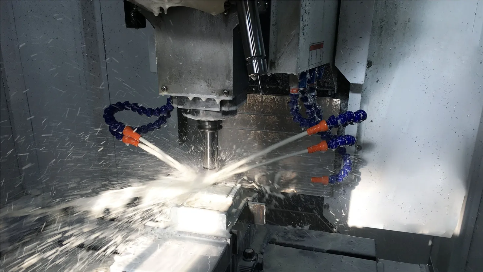
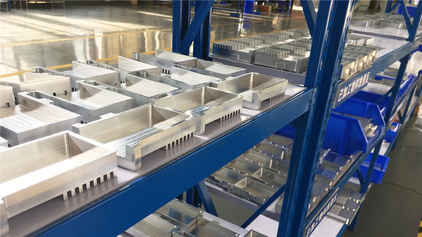
Dolph’s manufacturing page lists CNC machining, turning, waveguide forming and bending, plating, soldering/brazing and assembly capabilities. The company site also lists in-house RF vector and scalar measurement up to 100 GHz.
For supplier qualification or a custom build, review the Dolph Microwave manufacturing capabilities and send any drawing or inspection requirements with the RFQ.
Common buying questions
Quick answers before you ask for a quote
Does one attenuator cover the full 0.84–40 GHz range?
No. That is the combined coverage of the listed family. Each WRD model has its own frequency range. Select one row that covers your complete operating band.
Can I select the model from frequency alone?
Frequency narrows the choice, but it is not enough for release. Match WRD size, attenuation, CW power, cover/grooved flange designation, material and any mechanical constraints on the same configuration.
What should I send if my system uses pulsed RF?
Send the full frequency band, peak power, average/CW-equivalent power, pulse width, repetition rate or duty cycle, and the intended cooling/environmental conditions. Peak-power suitability must be checked separately from the published CW figure.
Can the finish or paint color be changed?
The current product note says other finishes and paint colors are available upon request. Put the required finish in the RFQ so it can be confirmed for the quoted configuration.
What files should I request before purchase approval?
Ask for the model-specific drawing or STEP file, the confirmed RF specification, flange/interface information, and any quality or inspection documents required by your purchasing process.
RFQ handoff
A short RFQ is enough if it contains the right data
Send what is already fixed in your system. If you have a mating drawing, existing part number or installation envelope, attach that too.
Technical files
PDF downloads and reference documents
The existing product-page PDF links are retained below. The double-ridged component catalog is added as a broader family reference.
Flange Type Designations Information
Reference for waveguide flange designations and mating-interface checks.
Download PDF →Double-Ridged Waveguide Components
Broader Dolph double-ridged waveguide product-family reference.
Download PDF →For procurement release, use the approved quotation and model-specific drawing as the final control documents for frequency, attenuation, CW/peak power, flange, material, finish, dimensions and acceptance requirements.