HOME » Waveguide, RF & Microwave Components » Microwave Sliding Short
Microwave Sliding Short
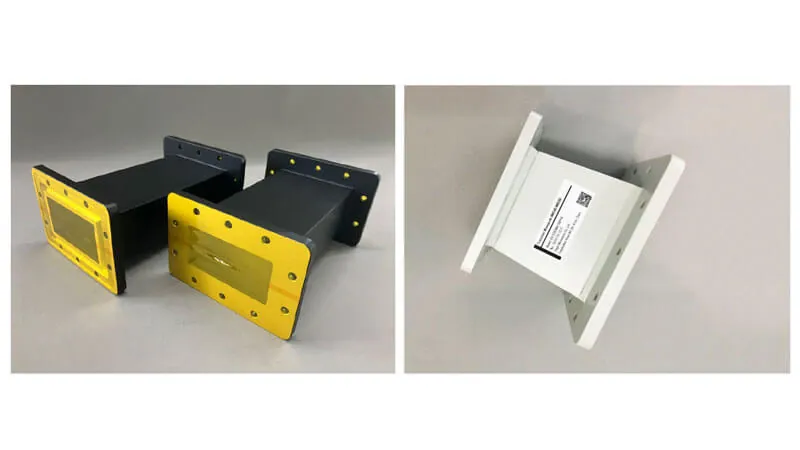
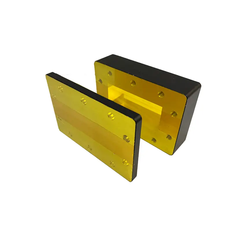
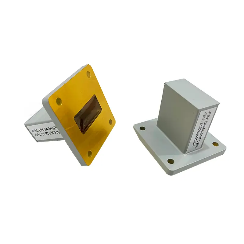
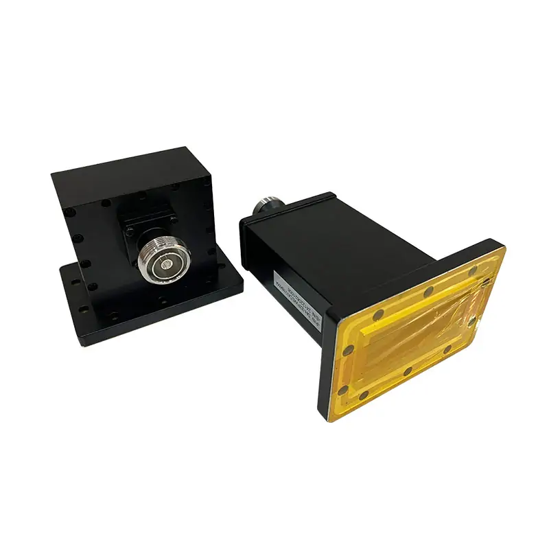
A microwave sliding short changes the position of a short-circuit termination inside a waveguide. The published family includes 915 MHz and 2450 MHz configurations, with power ratings selected by model. Specify frequency, WR size, flange, required adjustment stroke and CW power for quotation.
Adjustable microwave sliding short for industrial waveguide systems at 915 MHz and 2450 MHz. Published product data covers WR340, WR430 and WR975, with 6 kW, 10 kW and up to 20 kW CW handling power. The movable short circuit provides more than half a guide wavelength of adjustment at the lowest operating frequency. Standard and customized Al/Cu configurations are available.
Set the Short Position to Match Your Waveguide Setup
The movable short circuit is adjustable for more than half a guide wavelength at the lowest operating frequency. Send the frequency, WR size, CW power, flange interface and available installation space. We check the configuration before quotation.
915 MHz / 2450 MHz
WR340 / WR430 / WR975
Up to 20 kW CW
Published Product Data
The datasheet describes 915 MHz and 2450 MHz configurations and a wider family of waveguide sizes. Match the selected model to the operating frequency; the family maximum power does not apply to every row.
Industrial operating frequencies
915 MHz and 2450 MHz
Waveguide size
WR340, WR430 and WR975
Handling power
6 kW or 10 kW; configurations up to 20 kW CW, subject to model confirmation
Bandwidth
Full range
Material
Al/Cu
| Model | WR Type | Frequency (GHz) |
|---|---|---|
| DH-14WS… | WR650 | 1.13-1.73 |
| DH-22WS… | WR430 | 1.72-2.61 |
| DH-26WS… | WR340 | 2.17-3.30 |
| DH-32WS… | WR284 | 2.60-3.95 |
| DH-9WS… | WR975 | 0.76-1.15 |
Datasheet clarification: Frequency values are expressed in GHz. The source PDF labels this column MHz, which conflicts with the listed WR sizes and its 2450 MHz WR340 ordering example.
The PDF also prints 50 in every “VSWR Max.” row and 90, 70, 60, 60 and 110 under “Coupling (dB)” for WR650, WR430, WR340, WR284 and WR975 respectively. Those two fields require manufacturer clarification and are not presented here as verified acceptance limits. Request the selected model’s short-circuit performance, adjustment stroke and power rating before ordering.
Need a Fast Configuration Check?
Send frequency, WR size, CW power, flange code or drawing, and quantity. We check the fit before quotation.
Flange, Finish and Material
The PDF repeats the same flange and finish combination in four rows without identifying different models. It is shown once below. Confirm the mating flange drawing and required finish with the RFQ.

| Flange Type | Inside Finish | Body Finish | Material |
|---|---|---|---|
| FDP | Iridite per MIL-C-5541 | Anticorrosion Black Painted | Al/Brass |
Ordering Information
DH – 26 WSS 2450 P M A 6KW
DH
Dolph Microwave
26
Waveguide Type WR340
WSS
Sliding Short
2450
Freq. 2450 MHz
P
Flange Cover
M
Flange Grooved
A
Material Al
6KW
Handling Power 6KW CW
Choose the Component by What You Need It to Do
Use this sliding short when you need an adjustable short-circuit position in the waveguide.
For load impedance matching in a high-power industrial microwave line, use Microwave Tuners.
If you need to absorb reflected microwave power, use a Microwave Water Load.
For broader standard-waveguide sizes and general test work, compare the Waveguide Sliding Short range.
Have an Existing Part or Mating Flange Drawing?
Send the drawing, current part number or marked-up dimensions. We can review a standard model, replacement part or customized interface.
Send These Details With Your RFQ
Operating frequency or required band.
Waveguide type and mating flange designation or drawing.
Required CW power.
Material preference and available mechanical envelope.
Quantity and any PDF, STEP, sketch or existing part number.
Manufactured and Checked In-House
Manufacturing Capabilities
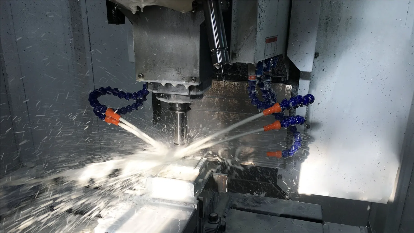
CNC and Waveguide Fabrication
Published capabilities include CNC machining, turning, forming, bending, plating, soldering and brazing.

Dimensional Verification
CMM equipment is part of the published manufacturing and inspection setup.

RF Test Support
Specify the required RF measurements, operating band, reference planes and acceptance limits with the RFQ.
Useful References Before You Finalize the RFQ
Quality and Warranty

Quality Documentation
Request the current quality-system certificate and product-specific inspection records with the RFQ.

RoHS Process Capability
The manufacturing page lists anodising and passivation with RoHS capability.

One-Year Warranty
Defects in material and workmanship are covered for one year from the date of delivery under Dolph Microwave’s published warranty terms.
Ready to Price the Sliding Short?
Send the operating frequency, WR size, CW power, flange interface and quantity. Add a drawing if the unit must replace an existing part.
Technical Documents
Use the product PDF for the published sliding-short data and the flange document when checking the mating interface.