The main horn antenna types are pyramidal, E-plane and H-plane sectoral, conical, corrugated, and ridged horns. TEM horns form a related family used for broadband and impulse measurements. Choose by usable frequency band, radiation pattern, polarization, and interface. “Standard gain,” “wideband,” and “circularly polarized” describe performance or operation, so they can overlap with these structural types.
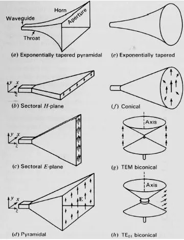
Horn antenna types at a glance
| Type | Structure | Typical selection reason | Check before ordering |
|---|---|---|---|
| Pyramidal | Rectangular waveguide flared in both principal planes | Directional linear polarization; standard-gain applications | Gain versus frequency, both beamwidths, and flange |
| E-plane or H-plane sectoral | Rectangular waveguide flared in one principal plane | A beam wider in one plane than the other | Beam orientation and full radiation pattern |
| Conical | Circular waveguide expanded to a circular aperture | Circular-waveguide feed integration | Excited mode, polarization, and pattern symmetry |
| Corrugated | Grooves along the inner wall | Low cross-polarization and controlled reflector illumination | Pattern, phase center, and performance across the band |
| Double-ridged | Two opposing internal ridges | Wideband, usually single linear polarization | Gain ripple and pattern quality as well as VSWR |
| Quad-ridged | Four ridges with suitable orthogonal feeds | Wideband dual-polarization applications | Port isolation and patterns for both polarizations |
| TEM | Flared conductors forming an open transmission-line transition | Broadband or short-pulse measurement | Impulse response, phase behavior, and antenna factor |
Pyramidal and sectoral horns
A pyramidal horn expands a rectangular waveguide in both the E and H planes. A sectoral horn expands it in one plane. These geometries let the designer control the aperture dimensions and the resulting beam shape.[1]
The E plane contains the electric-field direction and the main beam axis; the H plane contains the magnetic-field direction and that axis. They do not mean horizontal and vertical in every installation. Rotating a linearly polarized horn changes how those planes align with your test setup.
For a standard gain horn antenna, request gain data over the operating band rather than relying on a single nominal value. For a measurement reference, also ask for the calibration method, uncertainty, and reference plane. The words “standard gain” do not establish that an individual unit has been calibrated.
Conical horns
A conical horn expands from a circular waveguide into a circular aperture. Its shape does not by itself produce circular polarization: the feed and excited fields determine polarization. A circular aperture can therefore be used with a linearly polarized feed.
For reflector illumination, compare the actual E- and H-plane patterns, sidelobes, and phase-center position. A circular mouth is not evidence of identical patterns in both planes. Check how the horn connects to the polarizer, transition, or orthomode transducer in the feed assembly.
Corrugated horns
Corrugated horns use grooves to control the fields at the inner wall. Suitable designs support hybrid-mode behavior that can reduce cross-polarization and improve beam symmetry; these characteristics make them useful in radio astronomy and satellite reflector feeds.[2]
Groove dimensions are part of the electromagnetic design. There is no universal groove depth, flare angle, or cross-polarization limit that applies to every corrugated horn. Ask for measured patterns across your band and the angular region that illuminates the reflector.
A narrower standalone beam is not automatically a better dish feed. The feed must illuminate the reflector with the intended edge taper while limiting spillover. Compare the horn together with the reflector geometry and focal arrangement.
Double-ridged and quad-ridged horns
Internal ridges alter the waveguide’s modal behavior and can extend usable bandwidth. Double-ridged horns commonly serve wideband linear-polarization measurements; quad-ridged horns can support two orthogonal polarizations through separate feed paths. Published quad-ridged designs combine wide bandwidth with dual-polarization operation, but their results belong to the tested design.[3]
Check three bandwidths separately: impedance bandwidth, gain bandwidth, and pattern bandwidth. A horn may remain well matched while its beam shape or cross-polarization falls outside the limits your application needs. For dual-port units, request isolation and co- and cross-polarized patterns for both ports.
Bandwidth example: 2–18 GHz is a 9:1 frequency ratio. Using the arithmetic midpoint of 10 GHz, its fractional bandwidth is (18 − 2)/10 × 100 = 160%. These two figures describe the same interval with different conventions; neither proves constant gain or beamwidth. This is an illustrative calculation, not a product specification.
TEM horns
TEM horns use an open conductor structure rather than simply widening a closed rectangular or circular waveguide. NIST has developed ultra-wideband TEM horns for properties including short impulse duration, phase linearity, and nearly constant antenna factor.[4]
For pulse measurements, specify the waveform or frequency span and required time response. A gain curve alone does not show pulse distortion or ringing. Check the feed transition and mounting arrangement used for the reported results.
Polarization is a separate selection decision
Specify single linear, dual linear, right-hand circular, or left-hand circular polarization. A quad-ridged horn with two linear ports does not produce circular polarization merely because both ports exist; the excitation amplitudes and relative phase must support it.
For a linear or circular polarization horn assembly, request the supported polarization states and feed arrangement. For circular polarization, give an axial-ratio limit and its angular coverage; for dual linear polarization, specify both port isolation and cross-polarization requirements. These are different measurements.
What to check on the specification sheet
- Frequency: the complete required interval, including band edges.
- Gain: minimum or typical value versus frequency, units, and whether mismatch is included as realized gain.
- Pattern: half-power beamwidth in both planes, sidelobes, and cross-polarization.
- Match: maximum VSWR or minimum return loss over the stated band.
- Interface: waveguide and flange designation or coaxial connector, plus an outline drawing.
- Power and environment: CW or pulsed conditions, temperature, pressure, and any required protection.
- Test evidence: measured versus simulated data, test distance or transformation method, and calibration uncertainty where needed.
Do not compare gain in dBi with a bare “dB” value until the reference is identified. Likewise, a single power figure is incomplete without its operating conditions. Use the model-specific data for Dolph waveguide horn antennas to narrow the options, then confirm the required limits for the selected assembly.
Allow enough distance for measurements
A common far-field planning estimate is R ≈ 2D²/λ, where D is the largest antenna aperture dimension and λ is the free-space wavelength. NIST distinguishes this distance from near-zone measurements, where the horn’s effective gain depends on separation.[5]
Calculated example: with D = 0.20 m at 10 GHz, λ ≈ 0.03 m and 2D²/λ ≈ 2.7 m. This is a planning estimate, not a guarantee of measurement accuracy. The test antenna, chamber reflections, alignment, and required uncertainty can impose additional constraints.
Choosing a horn for a test range or feed assembly? Send the operating band, gain or beamwidth target, polarization, mating interface, and available space. For a reflector feed, include the reflector geometry and required illumination pattern.
Common selection questions
Table of Contents
Is a circular horn always circularly polarized?
No. “Circular” can refer to aperture shape. Confirm the polarization produced by the complete horn and feed assembly.
Is a wideband horn always the best choice?
No. A narrower-band horn may better match a gain, pattern, calibration, or size requirement. Select the design that meets all required limits over your operating band.
Can one horn replace several standard gain horns?
Possibly, if its calibrated gain or antenna factor, power handling, polarization, and patterns meet the measurement requirements across the full span. Confirm that the applicable test method permits the replacement before changing the setup.