
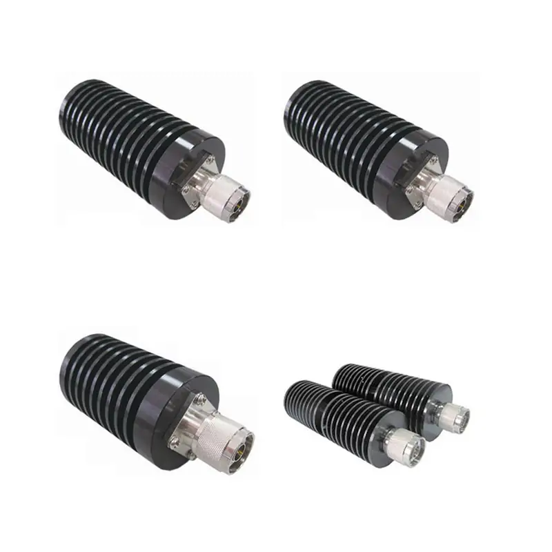
Coaxial Terminations
CL-series coaxial terminations with model-specific frequency, average and peak power, VSWR, connector and impedance data. Send your RF conditions for model matching.
Match the termination to the real RF load — not a family-wide headline.
Dolph Microwave supplies free-standing convection-cooled coaxial terminations for transmitter and antenna terminals, test loads, and matched ports in RF and microwave assemblies. Frequency, VSWR, peak power and connector limits are model-specific, so we match the part number to your operating conditions before quotation.
Send five inputs. We can narrow the range quickly.
Representative published configurations
These examples show why the final selection must be made by model row. Higher frequency and higher power are not available in the same configuration.
Complete Coaxial Termination Specifications
The full model table is retained below. Values are reproduced from the Dolph Microwave Coaxial Termination technical data. Confirm the final part number and current specification before order release.
| Model No | Avg Power (W) | Peak Power (kW) | Freq Range (GHz) | VSWR | Coax Connector Type | Impedance (Ω) |
|---|---|---|---|---|---|---|
| DH-124CL2S | 2 | 0.25 | DC-12.4 | 1.10-1.25 | SMA | 50 |
| DH-040CL2S | 2 | 0.25 | DC-4 | ≤ 1.20 | SMA | 50 |
| DH-400CL2S | 2 | 0.25 | DC-40 | 1.10-1.40 | SMA | 50 |
| DH-180CL2S1 | 2 | 0.25 | DC-18 | 1.10-1.30 | SMA | 50 |
| DH-180CL2S2 | 2 | 0.25 | DC-18 | 1.05-1.30 | SMA | 50 |
| DH-180CL2S3 | 2 | 0.5 | DC-18 | ≤ 1.25 | SMA | 50 |
| DH-400CL5S | 5 | 0.5 | DC-40 | ≤ 1.40 | SMA | 50 |
| DH-180CL10S | 10 | 0.5 | DC-18 | ≤1.45 | SMA | 50 |
| DH-060CL2N | 2 | 0.5 | DC-6 | 1.10-1.25 | N,SMA,BNC,TNC,7/16 | 50 |
| DH-180CL2N | 2 | 0.5 | DC-18 | 1.10-1.30 | N,BNC,SMA,TNC,7/16 | 50 |
| DH-030CL2 | 2 | 1 | DC-3 | ≤1.10 | 7/16 (M) | 50 |
| DH-080CL2N | 2 | 0.5 | DC-8 | 1.10-1.25 | N(M) | 50 |
| DH-060CL5N1 | 5 | 0.5 | DC-6 | 1.10-1.30 | N,BNC,SMA,TNC,7/16 | 50 |
| DH-060CL5N2 | 5 | 1 | DC-6 | 1.10-1.25 | N(M) | 50 |
| DH-180CL5N1 | 5 | 0.5 | DC-18 | 1.10-1.30 | N | 50 |
| DH-180CL5N2 | 5 | 0.5 | DC-18 | 1.10-1.30 | N,BNC,SMA,TNC | 50 |
| DH-060CL10N | 10 | 1 | DC-6 | 1.10-1.30 | N,BNC,SMA,TNC,7/16 | 50 |
| DH-100CL10N | 10 | 1 | DC-10 | 1.10-1.45 | N | 50 |
| DH-180CL10N1 | 10 | 1 | DC-18 | 1.10-1.40 | N,SMA,BNC,TNC | 50 |
| DH-180CL10N2 | 10 | 1 | DC-18 | 1.10-1.30 | N | 50 |
| DH-060CL25N | 25 | 1 | DC-6 | 1.10-1.25 | SMA,N,7/16,TNC,BNC | 50 |
| DH-100CL25N | 25 | 1 | DC-10 | 1.10-1.45 | N | 50 |
| DH-180CL25N | 25 | 1 | DC-18 | 1.15-1.35 | N,SMA,TNC | 50 |
| DH-060CL30N | 30 | 10 | DC-6 | 1.10-1.30 | N,SMA,7/16,TNC,BNC | 50 |
| DH-100CL30N | 30 | 1 | DC-10 | 1.10-1.45 | N | 50 |
| DH-040CL50N1 | 50 | 10 | DC-4 | 1.05-1.20 | N,SMA,7/16,TNC | 50 |
| DH-060CL50N | 50 | 1 | DC-6 | 1.10-1.25 | N,BNC,7/16,TNC | 50 |
| DH-100CL50N | 50 | 1 | DC-10 | 1.10-1.45 | N | 50 |
| DH-180CL50N1 | 50 | 1 | DC-18 | 1.10-1.45. | N,SMA | 50 |
| DH-180CL50N2 | 50 | 5 | DC-18 | 1.10-1.55 | N,7/16,SMA | 50 |
| DH-040CL80N1 | 80 | 10 | DC-4 | 1.05-1.25 | N,7/16,TNC | 50 |
| DH-180CL80N1 | 80 | 1 | DC-18 | 1.15-1.45 | N | 50 |
| DH-180CL80N2 | 80 | 5 | DC-18 | 1.15-1.55 | N | 50 |
| DH-040CL100N1 | 100 | 10 | DC-4 | 1.10-1.25 | N,7/16 | 50 |
| DH-180CL100N1 | 100 | 5 | DC-18 | 1.10-1.25 | N | 50 |
| DH-180CL100N2 | 100 | 5 | DC-18 | 1.10-1.55 | N | 50 |
| DH-040CL150N | 150 | 10 | DC-4 | 1.15-1.30 | N,7/16 | 50 |
| DH-180CL150N1 | 150 | 10 | DC-18 | 1.15-1.50 | N | 50 |
| DH-180CL150N2 | 150 | 5 | DC-18 | 1.15-1.55 | N | 50 |
| DH-040CL200N | 200 | 10 | DC-4 | 1.15-1.30 | N,7/16 | 50 |
| DH-100CL200N | 200 | 5 | DC-10 | 1.10-1.35 | N,7/16 | 50 |
| DH-040CL250N | 250 | 10 | DC-4 | 1.15-1.35 | N,7/16 | 50 |
| DH-100CL25N2 | 25 | 5 | DC-10 | 1.10-1.35 | N,7/16 | 50 |
| DH-040CL300N1 | 300 | 10 | DC-4 | 1.15-1.40 | N, 7/16 | 50 |
| DH-100CL300N | 300 | 5 | DC-10 | 1.10-1.35 | N,7/16 | 50 |
| DH-040CL400N | 400 | 10 | DC-4 | 1.15-1.45 | N,7/16 | 50 |
| DH-100CL400N | 400 | 10 | DC-10 | 1.10-1.50 | N,7/16 | 50 |
| DH-040CL500N1 | 500 | 10 | DC-4 | 1.15-1.40 | N,7/16 | 50 |
| DH-040CL500N2 | 500 | 5 | DC-4 | 1.15-.155 | N,7/16 | 50 |
| DH-040CL800N | 800 | 10 | DC-4 | 1.20-1.45 | N,7/16 | 50 |
| DH-040CL1000N | 1000 | 10 | DC-4 | ≤1.40 | N,7/16,L27 | 50 |
| DH-040CL1500N | 1500 | 10 | DC-4 | ≤1.40 | N,7/16,L27 | 50 |
| DH-040CL2000N | 2000 | 10 | DC-4 | ≤1.40 | N,7/16,L27 | 50 |
| DH-020CL1000N | 1000 | 50 | DC-2 | ≤1.30 | N,7/16,L27 | 50 |
| DH-020CL2000N | 2000 | 50 | DC-2 | ≤1.30 | N,7/16,L27 | 50 |
| DH-020CL3000N | 3000 | 50 | DC-2 | ≤1.30 | L27, 7/16,L36 | 50 |
| DH-010CL5000N | 5000 | 100 | DC-1 | ≤1.40 | L27, 7/16,L52 | 50 |
| DH-030CL1N | 1 | 0.5 | DC-3 | ≤1.20 | N,NBC | 75 |
| DH-030CL2N | 2 | 0.5 | DC-3 | ≤1.20 | N,NBC | 75 |
| DH-030CL5N | 5 | 0.5 | DC-3 | ≤1.20 | N,NBC | 75 |
| DH-030CL50N | 50 | 5 | DC-3 | ≤1.05 | N | 50 |
| DH-030CL150N | 150 | 5 | DC-3 | ≤1.05 | N | 50 |
| DH-085CL30N | 30 | 5 | DC-8.5 | ≤1.30 | N,SMA | 50 |
| DH-180CL50N3 | 50 | 5 | DC-18 | ≤1.55 | N,SMA | 50 |
| DH-180CL75N | 75 | 5 | DC-18 | ≤1.55 | N,SMA | 50 |
| DH-180CL150N3 | 150 | 5 | DC-18 | ≤1.55 | N | 50 |
| DH-040CL50N2 | 50 | 10 | DC-4 | ≤1.30 | N | 50 |
| DH-040CL100N2 | 100 | 10 | DC-4 | ≤1.30 | N | 50 |
| DH-040CL300N2 | 300 | 10 | DC-4 | ≤1.40 | N | 50 |
| DH-180CL50N4 | 50 | 5 | DC-18 | ≤1.55 | N | 50 |
| DH-180CL100N3 | 100 | 5 | DC-18 | ≤1.55 | N | 50 |
| DH-180CL200N | 200 | 5 | DC-18 | ≤1.55 | N | 50 |
| DH-0820CL300N | 300 | 5 | 0.8-2 | ≤1.20 | N | 50 |
| DH-0820CL350N | 350 | 5 | 0.8-2 | ≤1.20 | N | 50 |
| DH-1214CL300N | 300 | 12 | 1.2-1.4 | ≤1.20 | N | 50 |
| DH-040CL25N | 25 | 1 | DC-4 | ≤1.20 | N | 50 |
| DH-040CL30N | 30 | 1 | DC-4 | ≤1.20 | N | 50 |
| DH-040CL50N3 | 50 | 1 | DC-4 | ≤1.20 | N | 50 |
| DH-040CL80N2 | 80 | 1 | DC-4 | ≤1.20 | N | 50 |
| DH-040CL100N3 | 100 | 5 | DC-4 | ≤1.20 | N | 50 |
Source note: the published table contains several legacy connector/value labels and should be treated as the reference for initial selection, not as a substitute for final order confirmation.
Request Current Model ConfirmationPart number fields used in the published ordering example
Use the selected model row as the technical reference. The final suffix and interface are confirmed with sales before release.
If the job is not load termination, move to the right component family.
This avoids forcing a termination into an application that needs attenuation or interface conversion.
A short engineering check before quotation.
Send the operating conditions. We will work from the actual model limits.
Frequency band, average/peak power, connector and gender, impedance, quantity and any installation constraint are enough to start.







