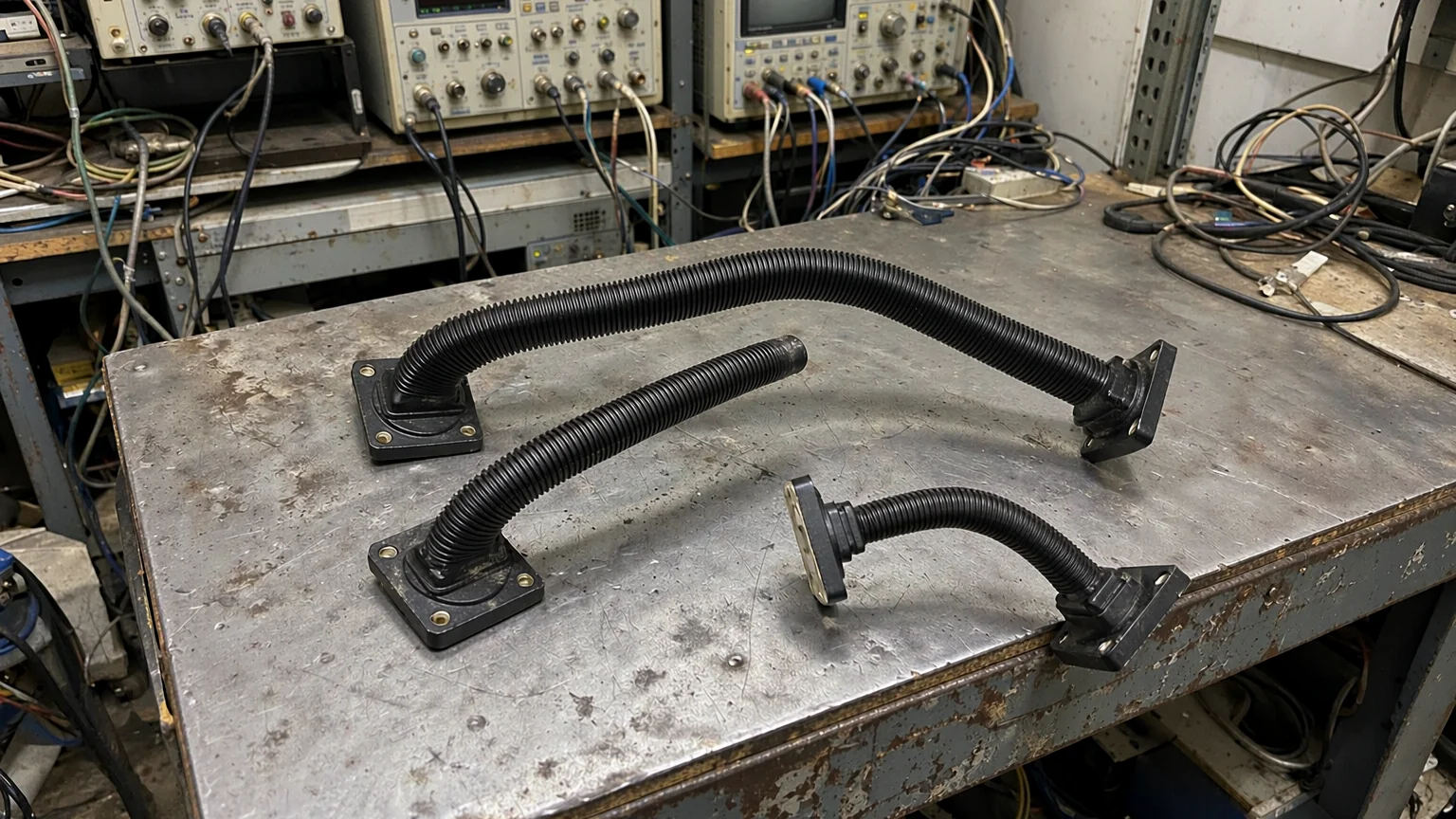
A circular waveguide refers to a waveguide with a circular cross-section.
The lowest order propagation mode in a circular waveguide is TE11, which provides minimal signal degradation.The possible TM modes in circular waveguides are TM01, TM02, TM11, and TM12.
The modes maintained by circular waveguides have many similarities with those of rectangular waveguides. For example, they can be classified as transverse electric modes (TE modes) without electric field components along the guiding axis, or as transverse magnetic modes (TM modes) without magnetic field components along the guiding axis.
Frequency Band
Frequency Range
Circular WaveguideDiameter, Inches (mm)
Cover Flange (Brass)MIL-F- 3922 UG
Flange Type
X
LOW
8.2-9.97
1.094 (27.79)
53-001 UG-39/U
Square
MID
8.5-11.6
0.938 (23.83)
HIGH
9.97-12.4
0.797 (20.24)
Ku
LOW
12.4-15.9
0.688 (17.48)
53-005 UG-1666/U
Square
MID
13.4-18.0
0.594 (15.08)
HIGH
15.9-18.0
0.500 (12.70)
K
LOW
17.5-20.5
0.455 (11.56)
54-001 UG-595/U
Square
MID
20-24.5
0.396 (10.06)
HIGH
24-26.5
0.328 (8.33)
Ka
LOW
26.5-33
0.315 (8.00)
54-003 UG-595/U
Square
MID
33-38.5
0.250 (6.35)
HIGH
38.5-40
0.219 (5.56)
Q
LOW
33-38.5
0.250 (6.35)
67B-006 UG-383/U
Round
MID
38.5-43
0.219 (5.56)
HIGH
43-50
0.188 (4.78)
U
LOW
40-43
0.210 (5.33)
67B-007 UG-383/U-M
Round
MID
43-50
0.188 (4.78)
HIGH
50-60
0.165 (4.19)
V
LOW
50-58
0.165 (4.19)
67B-008 UG-385/U
Round
MID
58-68
0.141 (3.58)
HIGH
68-75
0.125 (3.18)
E
LOW
60-66
0.136 (3.45)
67B-009 UG-387/U
Round
MID
66-82
0.125 (3.18)
HIGH
82-90
0.094 (2.39)
W
LOW
75-88
0.112 (2.84)
67B-010 UG-387/U-M
Round
HIGH
88-110
0.094 (2.39)
F
LOW
90-115
0.089 (2.26)
-UG-387/U-M
Round
HIGH
115-140
0.075 (1.91)
D
LOW
110-140
0.073 (1.85)
-UG-387/U-M
Round
HIGH
140-160
0.059 (1.50)
G
LOW
140-180
0.058 (1.47)
-UG-387/U-M
Round
HIGH
180-220
0.045 (1.14)
—
—
170-260
0.049 (1.25)
-UG-387/U-M
Round
—
—
220-325
0.039 (0.99)
-UG-387/U-M
Round
Note: The circular waveguide diameters provided correspond to each frequency band.