A waveguide component acceptance report needs six things: part identification, agreed limits, measured results, test conditions, calibration and uncertainty records, and an acceptance decision. Ask for results linked to the delivered serial numbers. An unlabeled plot or a model-wide specification sheet cannot replace those records.
Use this checklist as a purchasing guide. Your drawing, purchase order and agreed test plan set the requirements for the order. The numbers below are examples, not Dolph product specifications or universal acceptance limits.
Identify the parts and what was tested
List the part number, drawing revision, serial or batch number, purchase order, test date and report revision. Check that these identifiers match the delivered hardware. If parts have no individual serial numbers, agree on another way to link each required result to the inspected item.
For custom waveguide assemblies, record the full tested configuration, including bends, twists, adapters and flexible sections. Testing one straight section does not establish the performance of the assembled RF path.
Distinguish per-unit tests, sample tests and design-qualification evidence. If two units from a batch of ten were measured, identify both tested units. That is not individual testing of all ten. Use the sampling plan agreed for the order to decide whether those results support acceptance of the batch.
Show each requirement beside its result
| Report field | What it should show |
|---|---|
| Requirement | Drawing or specification clause, revision, limit and units. |
| Coverage | Frequency range, port or path, and operating state. |
| Result | Measured value; for a sweep, the worst observed value and its frequency. |
| Evidence | Trace or data-file reference linked to the tested unit. |
| Decision | Acceptance outcome under the agreed rule, plus any deviation reference. |
State whether the insertion-loss limit applies across the whole band or at named frequencies. A higher positive return-loss value in dB means less reflection. A VSWR closer to 1:1 also means less reflection. Make clear which quantity the limit uses.
Number the ports. S11 describes reflection at port 1; S22 describes reflection at port 2. S21 describes transmission from port 1 to port 2 under the stated measurement conditions. Include port assignments, reference impedances or normalization, and waveguide modes with exported S-parameter data.
Define the test scope before requesting a quote. Send Dolph your drawing revision, operating band and acceptance limits. Ask which checks and data files the quote can include for your component.
Show where and how the RF measurement was made
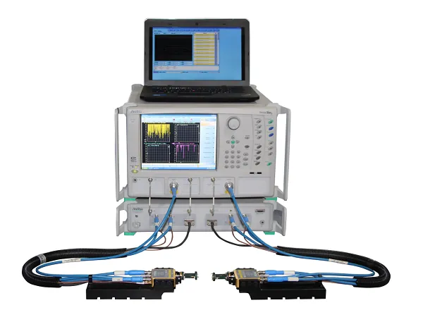
Ask for a connection diagram that marks the calibration reference planes. Each plane defines where the measurement applies. For any adapters or fixtures between that plane and the component, state whether their effects remain in the results or were removed through a documented correction.
List the vector network analyzer (VNA), instrument IDs, calibration method, standards or kit IDs, calibration date and verification results. Record sweep settings, test power and relevant environmental conditions. For narrow filter features, specify the frequency spacing and instrument settings used to resolve them.
An equally spaced sweep from 8 to 12 GHz with 401 points has 400 intervals: (12 − 8) / 400 = 0.01 GHz, or 10 MHz. A feature between the points may be missed. Choose spacing that suits the component and its limits. This is a calculation example; 401 points is not a universal requirement.
NIST’s WR15 study shows how dimensional uncertainties in waveguide calibration standards propagate into calibrated scattering parameters.[1]
Use Dolph’s published testing capability to identify the type of setup to discuss. Then ask for the setup and evidence specific to your order. An equipment list does not show that a delivered unit passed its tests.
Check traceability, uncertainty and the decision rule
A calibration sticker alone does not establish traceability for a reported result. Ask for the documented calibration chain and its associated uncertainties. NIST defines traceability as a property of the measurement result, not the instrument alone.[2]
If the report states expanded uncertainty U, ask for its units, coverage factor k and the basis for the stated coverage. A value of k = 2 does not automatically mean 95% coverage. That interpretation depends on the statistical assumptions.[3]
Agree before testing on how uncertainty affects acceptance. JCGM 106 distinguishes simple acceptance from rules that use a guard band to place the acceptance boundary inside the specification limit.[4]
Illustrative insertion-loss example: the upper limit is 0.20 dB, the measured result is 0.18 dB, and expanded uncertainty is 0.03 dB. A simple comparison of the measured value with the limit gives a pass. If the agreed rule requires measured value + U ≤ limit, the calculation is 0.18 + 0.03 = 0.21 dB. The result does not meet that guard-band acceptance rule. This does not prove that the true loss exceeds the limit.
Need a customer-specific report format? Send the required fields, file formats and decision rule with your inquiry. Ask Dolph to confirm the reporting scope before you order.
Choose checks that match the component’s function
Use the agreed specification to select additional measurements. Do not use the same pass/fail checklist for every component.
- Bends, twists and assemblies: check interface orientation, critical dimensions, insertion loss and reflection over the ordered band.
- Filters and diplexers: check passband limits, rejection at specified frequencies and isolation between the relevant ports.
- Directional couplers: measure coupling, directivity and port matching. Identify the terminations used on unused ports.
- Waveguide rotary joints: record RF results at the required rotation states, including specified loss or phase variation. One stationary measurement does not cover a limit that depends on rotation.
- Pressurized or high-power components: include the pressure, leakage, power and thermal records required by the order. Identify the test conditions and procedures.
Record flange type, critical dimensions, orientation, visible damage and any required material or coating evidence. Tie each inspection to the drawing requirements. Do not add a generic plating thickness or dimensional tolerance.
Keep low-power RF results separate from power-handling, environmental and life-test evidence. For each special test, state whether it was performed on the delivered unit, a sample or a qualification article. Mark any test that was not performed. A routine RF sweep does not imply that these other tests were completed.
Keep usable data and document exceptions
Request a readable PDF and numerical sweep data in the agreed format. Touchstone files can preserve S-parameters; CSV files may suit tabulated results. Include units, port definitions and a clear link to the component and report revision in each file.
Record failures, adjustments, repairs and retests, and keep the earlier results. State what changed, who authorized the disposition and which data support release. Name the report’s preparer and authorized reviewer, and identify the organization responsible for testing.
A declaration of conformity may say that requirements were met without providing the measurements needed for this review. If you need both a declaration and a detailed acceptance report, list both as order deliverables.
Agree on the report format, test coverage and acceptance rule before ordering. Resolve missing unit IDs, uncovered frequency ranges and unexplained deviations before release. For any result near its limit, check the uncertainty and decision rule before signing it off.
Include the report in your waveguide RFQ. Send the quantity, drawing, frequency band, required tests and delivery documents. Dolph can then quote the component and reporting scope together.