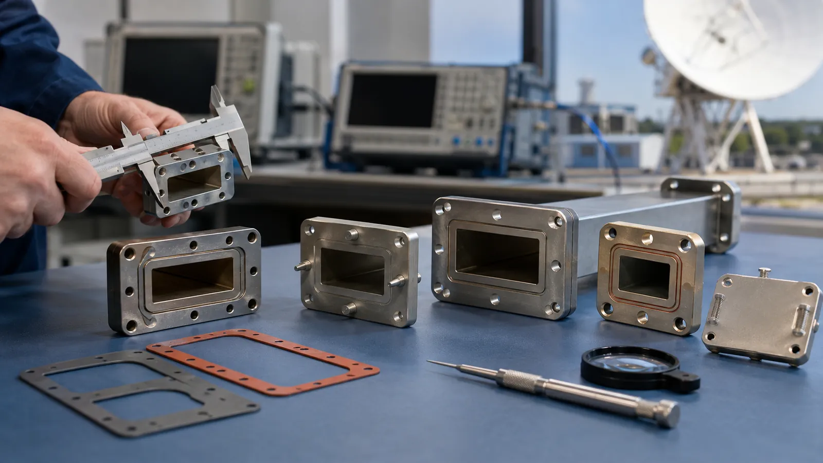
Choose a waveguide flange by its complete interface drawing, not the WR size alone. Match the RF aperture, bolt and alignment-hole pattern, mating face, gasket groove and fasteners. Two parts marked WR90 can carry the same waveguide size yet require different flange interfaces.
IEC 60154-2 covers mechanical dimensions and compatibility for ordinary rectangular waveguide flanges. Its scope does not make every flange used with one WR size interchangeable.[1]
EIA Standard
Table of Contents
Flange Code Matching
Keep three identifiers separate: the waveguide size, the flange designation and the governing drawing or specification revision. A WR number identifies a rectangular waveguide size; it is not a complete bolt-pattern or sealing specification.
Do not treat EIA, IEC and U.S. military designations as interchangeable names. For example, DLA publishes MIL-DTL-3922/53 for a particular square, four-hole cover-flange design. A procurement requirement must identify the applicable detail sheet, revision and part configuration.[2]
Dolph’s EIA/IEC flange reference lists WR90 with R100, WR75 with R120 and WR62 with R140. Those size cross-references help find a drawing; they do not prove that two listed flange styles mate.
| Waveguide reference | Examples in the Dolph flange table |
|---|---|
| WR90 / R100 | UBR100, PBR100, CPR90F and CPR90G. |
| WR75 / R120 | UBR120, PBR120, CPR75F and CPR75G. |
| WR62 / R140 | UBR140, PBR140, UDR140 and PDR140. |
Copy the complete code, including suffixes, onto the purchase specification. Do not infer a thread standard from “/U,” or infer pin locations from an abbreviated family name. If a vendor uses a different naming convention, compare dimensioned interfaces before accepting the substitution.
Bolt Hole Layout
For rectangular patterns, compare each hole’s position from the drawing datums. A single pitch-circle diameter cannot fully describe every square or rectangular flange. Check clearance versus tapped holes, thread size and pitch, counterbores, alignment pins and usable screw engagement.
Alignment pins locate the RF aperture; bolts provide clamping. Bolt clearance alone may allow enough movement to change the joint’s RF behavior. NIST research shows that test-port aperture errors and flange misalignment affect rectangular-waveguide calibration.[3]
Use the drawing’s positional and dimensional tolerances. There is no single ±0.1 mm acceptance rule for all flange sizes and frequencies. A mismatch calls for identification and measurement; it is not, by itself, evidence of a counterfeit part.
Cover Flange Types
A waveguide cover flange is a mating flange with an RF opening. It is not the same as a solid protective cover or a blanking plate. Check whether its face is flat, grooved or intended to mate with a specified choke flange.
A contact joint relies on the intended conductive interface around the aperture. A choke joint uses a designed geometry that can include a controlled gap. Do not fill a choke feature with sealant or add a gasket merely because a gap is visible; follow the matched flange-pair drawing.
IEC Types
Type Name Verification
Record the full IEC flange designation and the relevant standard edition. UBR100 and PBR100 are different entries in Dolph’s R100 reference row; “R100 flange” alone leaves the interface unspecified.
Check whether the assembly is full-height, reduced-height or custom. The flange outline can resemble another part while the RF aperture differs. Request both mating drawings when replacing equipment from another supplier.
Dimensional Table Matching
Convert the actual drawing dimension rather than treating a size label as an exact measurement. One inch equals exactly 25.4 mm, so one mil, or 0.001 inch, equals 0.0254 mm.[4]
| Example internal broad wall | Conversion |
|---|---|
| WR90: 0.900 inch | 22.860 mm. |
| WR75: 0.750 inch | 19.050 mm. |
| WR62: 0.622 inch | 15.7988 mm, commonly displayed as 15.80 mm. |
These are aperture-width examples, not flange outside dimensions or machining tolerances. Retain the drawing’s controlling unit and tolerance; a rounded metric display must not silently become a new acceptance limit.
Mixed-Standard Risks
Compare the aperture, face geometry, hole pattern, pin fit, groove, finish and hardware as one interface. Matching only the aperture leaves the seal and clamp arrangement unresolved. Matching only the bolts can leave an RF step or offset.
Do not assume all North American interfaces use the same inch thread or all IEC interfaces use metric threads. The released drawing determines the fastener. Stop if a screw binds, a pin will not seat or the faces require force to align.
A custom transition assembly can accommodate two specified interfaces when a direct joint is unsuitable. Its added length, RF performance, pressure boundary and mounting loads still need approval.
Gasket Fit
Gasket Groove Matching
Select a waveguide gasket for the actual groove, mating face and required function. A pressure seal and a conductive RF seal are not automatically the same component. Check the exact compound, cross-section, temperature range, gas compatibility and compression requirements.
For a simple face seal, nominal compression is (free seal height − closed gland height) / free seal height × 100%. An illustrative 1.5 mm seal in a 1.2 mm closed gland has 20% nominal compression. A 1.2 mm seal in that same gland has zero nominal compression; making it thinner does not fix a sealing problem.
The 20% calculation is not a universal recommended squeeze. Check the seal supplier’s approved range and the tolerance stack. Groove width also affects available space and gland fill; seal swell, thermal expansion and deformation can change the result.
Sealing Surface Inspection
Inspect the face and groove for burrs, dents, corrosion, plating damage and particles. Measure flatness and surface finish against the drawing rather than applying a generic roughness value to every flange.
Clean with a method compatible with the finish and seal. Do not use abrasive paste or field grinding to make a mismatched pair fit. Rework can change flatness, coating thickness and the aperture edge; obtain an approved repair procedure or replace the damaged part.
Use the specified fastener grade, lubrication condition, tightening sequence and torque. A bolt bottoming in a blind hole can reach torque without creating the required clamp load. Reinspect the seal position and face seating after assembly.
Leak Risk Points
Define the gas, pressure differential, temperature, test method and acceptance limit before testing. ISO 20485 describes tracer-gas leak-testing techniques; it does not supply one universal leakage limit for every waveguide joint.[5]
For a numerical comparison only, a measured rate of 5 × 10⁻⁷ mbar·L/s is 50 times a specified limit of 1 × 10⁻⁸ mbar·L/s. Neither number is a default Dolph requirement. State the tracer gas and test conditions so results can be compared meaningfully.
Leak tightness does not establish insertion loss or return loss. Measure RF performance over the required band after the joint is assembled, and repeat the relevant tests after disassembly or seal replacement. Record the flange drawings, seal part number, assembly conditions and measured results in the component acceptance report.